
See the warning at the beginning of the section Relieving pressure in the power supply system of gasoline engines.
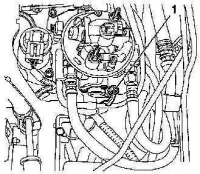
Fuel injector
Before finally establishing your opinion about the failure of the injector, try adding any of the additives approved by car engine manufacturers to the fuel. Also make sure the fuel tank is clean.
1. Relieve the pressure in the supply system (see Relieving pressure in the power supply system of gasoline engines), then disconnect the negative cable from the battery.
2. Loosen the clamp and disconnect the intake duct from the throttle body cover. Disconnect from a cover also vacuum hoses and hoses of ventilation of a crankcase. Turn out fixing screws and remove a cover with a sealing ring from the case of a throttle.
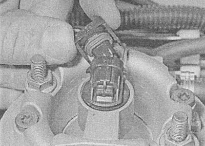
3. Release a clamp and disconnect an electroconducting from an injector.
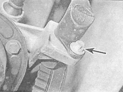
4. Remove the fixing screw.
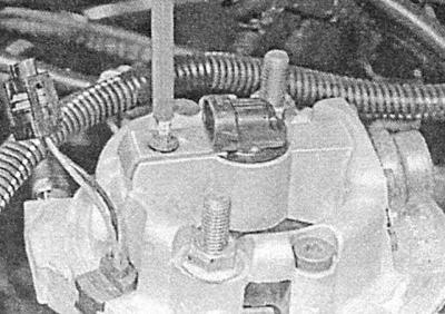
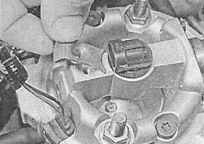
5. Remove the injector mounting plate.
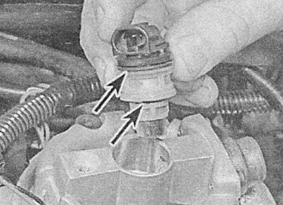
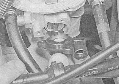
6. Remove the injector assembly with the sealing ring from the seat in the throttle body. Discard the O-rings - they must be replaced during installation without fail.
7. Installation is carried out in the reverse order - do not forget to replace the sealing ring. Make sure that the injector mounting bolt is tightened to the required torque.
Fuel pressure control
At the time of writing this manual, pressure regulator components are not available separately on the aftermarket. In the event of failure, replace the throttle body assembly. Despite the fundamental possibility of disassembling and cleaning the regulator, disassemble it only as a last resort.
1. Relieve the pressure in the supply system (see Relieving pressure in the power supply system of gasoline engines), then disconnect the negative cable from the battery.
2. Loosen the clamp and disconnect the intake duct from the throttle body cover. Disconnect from a cover also vacuum hoses and hoses of ventilation of a crankcase. Turn out fixing screws and remove a cover from the case of a throttle in gathering with a sealing ring.
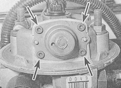
3. Mark the position of the regulator cover relative to the throttle body with a marker. Loosen the screws securing the regulator cover.
4. Remove the cover, remove the spring seat and spring, take out the diaphragm, try to remember the installation position of the components. Remove all traces of dirt, check the condition of the diaphragm - if there are signs of wear or damage, replace the throttle body.
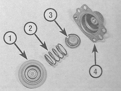
1 - Diaphragm
2 - Spring
3 - Spring seat
4 - Cover
5. Installation is carried out in the reverse order. Make sure all fasteners are tightened to the correct torque.
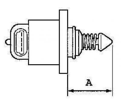
Idle stabilization stepper motor
1. Disconnect the negative cable from the battery.
2. To ensure adequate access, loosen the clamp and disconnect the intake duct from the throttle body cover. Disconnect the air and vacuum hoses from the cover, unscrew the fixing screws and remove the cover from the housing together with the sealing ring.
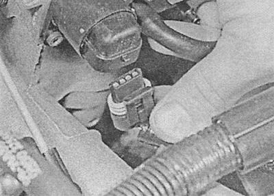
3. Release the latch and disconnect the electrical wiring from the stepper motor mounted in front of the throttle body.
4. Remove the mounting screws and carefully remove the electric motor from the housing - try not to damage the plunger. Remove the sealing ring from the electric motor - it must be replaced during assembly without fail.
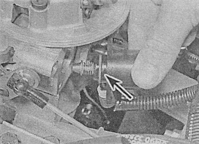
5. Installation is carried out in the reverse order. To check the proper functioning of the idle speed stabilization system, measure the amount of protrusion of the plunger (A) from the electric motor, - the result of the measurement should be no more than 28 mm.
Position sensor (potentiometer) throttle valve (TPS)
1. Disconnect the negative cable from the battery. Also disconnect the wiring from the TPS sensor.
2. Remove the mounting bolts and remove the TPS sensor from the throttle body.
3. Installation is carried out in the reverse order. Check that the potentiometer is correctly engaged with the throttle shaft. Before screwing in the fixing bolts, grease their threaded part with an anaerobic sealant. After tightening the bolts to the required torque, connect the electrical wiring to the sensor.
Coolant temperature sensor (ECT)
The coolant temperature sensor is screwed into the rear of the intake manifold. For instructions on how to remove and install the sensor, see Check of serviceability of functioning, removal and installation of electric components of a chain of management of the engine cooling system.
Absolute pressure sensor in the pipeline (MAP)
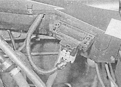
The MAP sensor is mounted on the bulkhead of the engine compartment, to the left of the throttle body.
1. Turn off the ignition, disconnect the electrical wiring and vacuum hose from the sensor. The sensor can now be removed from the bracket.
2. Installation is carried out in the reverse order.
Crankshaft position sensor (CKP)
1. The sensor is installed on the rear wall of the cylinder block and can be accessed from under the car. Apply the parking brake, jack up the front of the vehicle and place it on jack stands.
2. Walk along the electrical wiring from the sensor, releasing the harness from the intermediate clamps and remembering the route of its laying. Disconnect the connector - the sensor is removed together with part of the harness.
3. Turn out a fixing bolt and remove the gauge.
4. Installation is carried out in the reverse order. Make sure the fasteners are tightened to the correct torque. Make sure the harness is routed correctly.
5. Finally, measure the distance between the sensor and the gear rotor on the crankshaft pulley - if the result exceeds 1.0±0.7mm, replace the sensor mounting bracket.
Knock sensor (KS)
The knock sensor is mounted on the rear wall of the cylinder block and can be accessed from under the vehicle.
1. Apply the parking brake, jack up the front of the vehicle and place it on jack stands.
2. Walk along the electrical wiring from the sensor, releasing the harness from the intermediate clamps and remembering the route of its laying. Disconnect the connector - the sensor is removed together with part of the harness.
3. Turn out a fixing bolt and remove the gauge.
4. Installation is carried out in the reverse order. Before installation, make sure that the mating surfaces are absolutely clean and dry. Tighten fasteners to the required torque. Check for correct wiring.
Electronic engine control module (ECM)
The ECM is located behind the battery on the left side of the engine compartment.
1. Disconnect the negative cable from the battery and remove both wipers (see chapter Onboard electrical equipment).
2. Remove the protective cover from the module.
3. Pull up to release the module from the support bracket and disconnect the electrical wiring from it.
Before installing the module, you can clear the processor memory in order to remove the recorded diagnostic codes from it in the conditions of a car service workshop.
4. Installation is carried out in the reverse order.
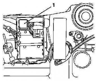
Injection relay
1. The injection system relay is located in the mounting block located in the engine compartment.
2. Remove the cover from the mounting block. The system relay is colored magenta. Make sure the ignition is off, then release the relay from the block.
3. Installation is carried out in the reverse order.
Air conditioning switch
The sensor-switch of the air conditioning system is screwed into one of the lines of the refrigeration path and cannot be removed without first discharging the system (see chapter Cooling, heating systems). In view of the foregoing, the replacement of the sensor-switch should be carried out in the conditions of a car service workshop.
Visitor comments