
Starting device
When the control handle is pulled out, the choke valve closes and the throttle valve opens slightly as a result of the movement of the control lever and the fast idle cam.
Under the influence of the vacuum created under the air damper when the engine is started, fuel is supplied from the main metering system. Then the air damper opens slightly, overcoming the resistance of the control rod spring. The amount of opening of the air damper is set by a pneumatic actuator installed in the area of the throttle body.
Idle systems
The carburetor has two idle systems: main and auxiliary. In the main idling system, the fuel coming from the main fuel jet (see picture), is supplied to the fuel jet 1 of the main idling system. At the outlet of the jet 1, the fuel is mixed with the air entering through the air jet 2. The emulsion exits under the throttle valve through the slot of the transition system at the throttle valve, passes through the channel, the cross section of which is regulated by the mixture quality screw 13. Further along the channel, the air-fuel emulsion enters the outlet channel of the idle system after the adjusting screw 10 of the amount of the mixture, which is part of the auxiliary idle system. In the auxiliary idling system, fuel is taken from the well directly from the float chamber and supplied to the idle fuel jet 5 and mixed with the air supplied by the air jet 4 of this system. The mixture passes through the tube of the auxiliary idle system and through the channel, the cross section of which is regulated by the mixture quantity screw 10, is fed into the throttle space through the outlet 9 of the idle system.
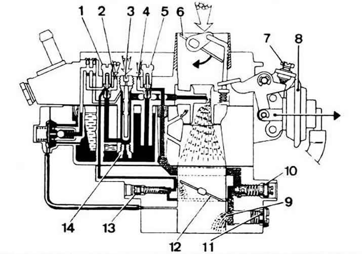
Cold start system and idling system:
1 - fuel jet of the main idling system;
2 - air jet of the main idling system;
3 - main air jet;
4 - air jet of the auxiliary idling system;
5 - fuel jet auxiliary idle system;
6 - air damper;
7 - adjusting screw for slightly opening the air damper;
8 - pneumatic actuator of the air damper;
9 - outlet of idle systems;
10 - adjusting screw for the amount of the mixture;
11 - threaded plug;
12 - throttle valve;
13 - quality adjusting screw (composition) mixtures;
14 - main fuel jet.
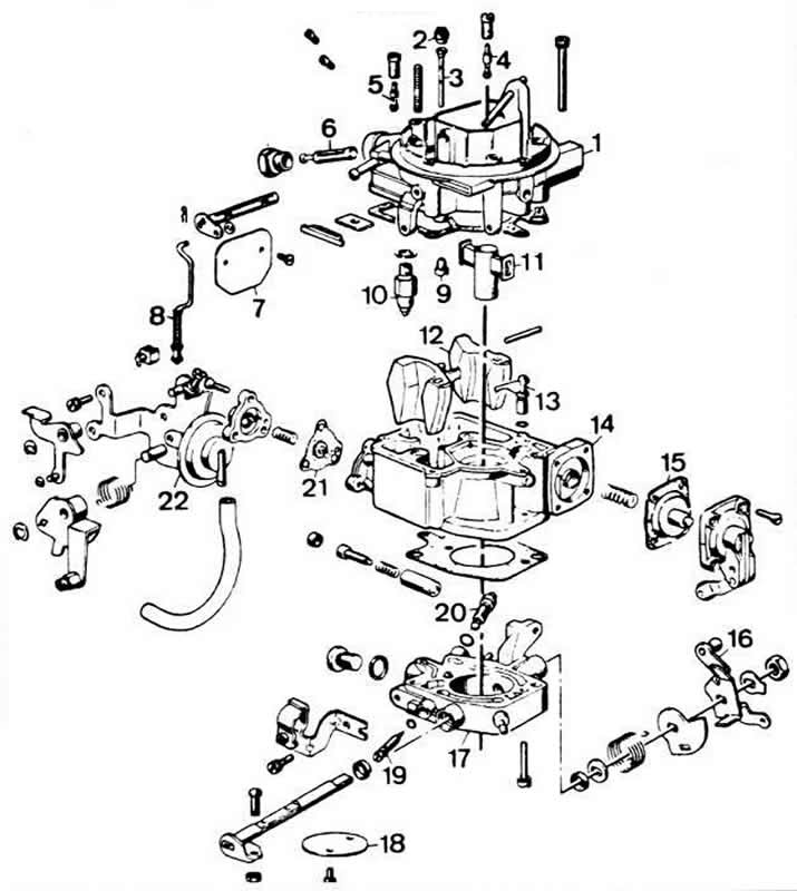
Details of the Weber 32 TL carburetor:
1 - carburetor cover;
2 - main air jet;
3 - emulsion tube;
4 - fuel jet auxiliary idle system;
5 - fuel jet of the main idling system;
6 - fuel filter;
7 - air damper;
8 - air damper control rod with a spring;
9 - main fuel jet;
10 - needle valve;
11 - atomizer;
12 - float;
13 - spray accelerator pump;
14 - carburetor body;
15 - accelerator pump diaphragm;
16 - throttle control lever;
17 - throttle body;
18 - throttle valve;
19 - quality adjusting screw (composition) idle mixtures;
20 - adjusting screw for the amount of idle mixture;
21 - diaphragm economizer power modes;
22 - air damper pneumatic actuator.
Visitor comments