
General information
The design of the exhaust system for 1.2L models
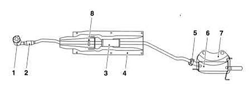
1 - catalytic converter
2 - Flexible connector
3 - Intermediate muffler (resonator)
4 - Heat shield
5 - Flange connection
6 - Main muffler
7 - Heat shield
8 - Clamp connection
The design of the exhaust system models 1.4, 1.6 (SOHC) and 1.7 l
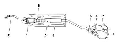
1 - catalytic converter
2 - Flexible connector
3 - Intermediate muffler (resonator)
4 - Heat shield
5 - Flange connection
6 - Main muffler
7 - Heat shield
8 - Clamp connection
The design of the exhaust system models 1.6 (DOHC), 1.8 and 2.0 l
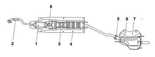
1 - catalytic converter
2 - Flexible connector
3 - Intermediate muffler (resonator)
4 - Heat shield
5 - Flange connection
6 - Main muffler
7 - Heat shield
8 - Clamp connection
The exhaust system of all models under consideration consists of three sections: intake, middle (intermediate) and back. The main elements of the system are: exhaust pipe, catalytic converter, mufflers (intermediate and main), connecting tubular sections, mounting clamps, as well as support brackets and rubber loops, through which the exhaust assembly is suspended from the bottom of the car (see illustrations Design of the exhaust system for 1.2L models, The design of the exhaust system models 1.4, 1.6 (SOHC) and 1.7 l and The design of the exhaust system models 1.6 (DOHC), 1.8 and 2.0 l). Sections of the system are mated with each other by means of one clamp connection (front section with intermediate) and one flange (intermediate section from the back). The junction of the middle and rear sections of the system is spring-loaded, which makes it possible to compensate for the backlash that occurs during the movement of the car; in order to reduce the level of vibrations, a flexible insert is usually included in the receiving section of the system. Improper installation of components and sections of the system leads to an increase in the level of noise and vibration transmitted to the car body.
Regularly inspect the entire system for signs of corrosion, deformation and mechanical damage. Check fastener tightness. Violation of the tightness of the components and their joints is fraught with the ingress of exhaust gases into the vehicle interior. Defective components and sections must be replaced.
If the system is severely damaged by corrosion, a cutting torch may be required to separate its sections (alternatively, you can use a hacksaw or a pneumatic chisel - do not forget to wear safety goggles and gloves).
System repair should be carried out in the following order:
1. When removing components, move along the system path in the direction from the exhaust pipe to the engine.
2. Lubricate the fasteners to be loosened with penetrating oil.
3. Prepare the necessary replacement gaskets, hanging loops, clamps and fasteners in advance.
4. Lubricate the threaded part of the fastener with anti-seize sealant before installation.
5. When installing components, make sure that there is sufficient clearance between the sections of the system and nearby suspension / body elements. Pay special attention to the correct installation and secure fastening of the heat shield of the catalytic converter.
Removing
Each section of the system can be dismantled separately. It is also possible to remove the entire exhaust tract assembly. Even if only a single section needs to be replaced, it is easier to dismantle it after first removing the entire assembly.
1. Jack up the front of the car and place it on jack stands (with the appropriate equipment of the site, you can drive the car onto a flyover or viewing hole). If equipped, remove the crankcase protection.
Receiving section
Petrol models
Models with SOHC engines
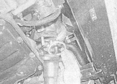
1. Turn out spring-loaded bolts of a flange of fastening of a pipe to a final collector.
2. Release a collar of fastening of a reception pipe to average section. Remove the seal. Separate the pipe from the middle section and remove it from under the car.
Models with 1.4 and 1.6 L DOHC engines
1. Turn out bolts of a flange of fastening of a pipe to a final collector.
2. Give a nut of fastening of a reception pipe to a basic arm, remove a washer, the plug and a rubber support.
3. Release a fixing collar, separate a reception pipe from an intermediate section and take it from under the car. Remove the sealing gasket of the flange joint with the exhaust manifold.
Models with 1.8 and 2.0 L DOHC engines
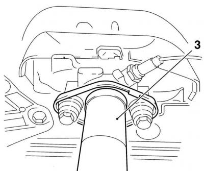
1. Walk along the electrical wiring from the lambda probe to the connector and disconnect the latter - try to remember the order of laying the harness. There is no need to remove the sensor - the pipe can be removed assembled with it.
2. Turn out bolts of flange connection of a reception pipe to a final collector.
3. Give nuts of fastening of a reception pipe to a basic arm and remove an assembly plate.
4. Release a fixing collar, separate a reception pipe from an intermediate section and take it from under the car. Remove the sealing gasket of the flange joint with the exhaust manifold.
Diesel models
The intake section includes a catalytic converter.
1. Release a collar of fastening of a reception pipe to average section of system of release.
2. Separate a reception pipe from assembly of a turbocharger, remove a sealing lining.
3. Separate a reception pipe from average section and take it from under the car.
Middle section
All models
1. Release a collar of fastening of an average section to a reception pipe and give spring-loaded bolts of fastening it to a back part.
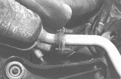
2. Remove the middle section from the rubber hangers, disconnect it from the downpipe and rear section, and remove it from under the vehicle.

Rear section
All models
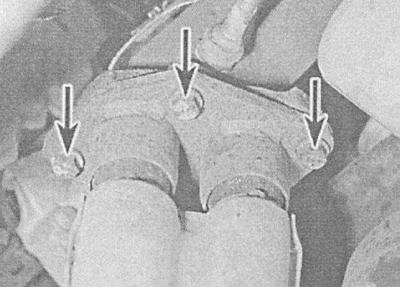
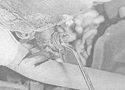
1. Remove the spring-loaded bolts from the rear section flange connection to the middle section.
A - Flange connection of the middle section of the exhaust system to the rear section
B - Rubber hangers of the support brackets of the rear section of the exhaust system
A.
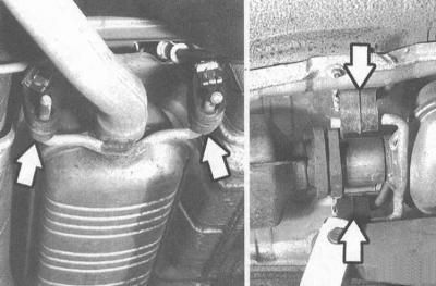
B.
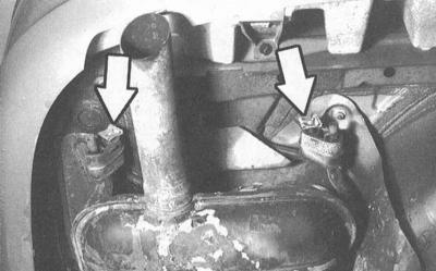
2. Remove the rear section from the rubber hangers and separate it from the intermediate section - the sealing gasket must be replaced without fail.
Complete exhaust system
Models with SOHC engines
1. Turn out spring-loaded bolts of flange connection of a reception pipe with a final collector.
2. Remove the system from the rubber hangers and remove it from under the car; the sealing gasket of the flange connection must be replaced without fail.
Models with 1.4 and 1.6 L DOHC engines
1. Loosen the nuts securing the downpipe to the support bracket, remove the mounting plate/washer and rubber support.
2. Turn out bolts of fastening of a reception pipe to a collector, remove a sealing lining, - at assembly the lining is subject to replacement without fail.
3. Remove the system from the rubber hangers, lower it and remove it from under the car.
Models with 1.8 and 2.0 L DOHC engines
1. Walk along the electrical wiring from the lambda probe to the connector and disconnect the latter - try to remember the order of laying the harness. There is no need to remove the sensor - the pipe can be removed assembled with it.
2. Give nuts of fastening of a reception pipe to a basic arm, remove an assembly plate / a washer and a rubber support.
3. Remove the bolts of the flange connection of the intake pipe with the exhaust manifold, remove the sealing gasket - during assembly, the gasket must be replaced without fail.
4. Remove the system from the rubber hangers, lower it and remove it from under the car.
Thermal screens
The screens are attached to the bottom of the car with various nuts and bolts. Screens are removed after preliminary dismantling of the corresponding section of the exhaust system. If the removal is made in order to provide access to the element located under it, it will be enough just to release the fasteners and lower the screen shield down.
Installation
Each section is installed in the reverse order of its dismantling. Pay attention to the following points:
1. Before installation, carefully clean the mating surfaces of the sections, prepare replaceable sealing gaskets.
2. Check the condition of the rubber hangers, replace the defective components.
3. If the sections are mated without the use of gaskets, coat the joint with a special sealant.
4. Before tightening fasteners, make sure that the system is fixed in all suspensions, and its components do not come into contact with body elements and vehicle suspension parts.
Visitor comments