
Crankcase ventilation system (PCV)
All models
The system components do not require special maintenance beyond the normal checks of the condition of the hoses and their fittings in accordance with the Vehicle Routine Service Schedule (see chapter Current service).
Evaporative Emission System (EVAP) - petrol models
Examination
Always check the condition of the vacuum hoses first, which are the most common cause of system failure due to looseness, disconnection or damage (refer to the hose routing diagram on your vehicle's VECI label). Replace damaged hoses if necessary. Full diagnostics of the system is possible only with the use of specialized equipment connected to the DLC connector (see The principle of operation of fuel injection systems). In the event of failure, the purge valve and/or carbon adsorber must be replaced.
Replacement
Carbon adsorber
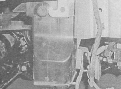
The carbon adsorber is installed under the right front fender of the car.
1. In order to provide adequate access to the canister, set the parking brake, then jack up the front of the car and place it on props. Remove the right front wheel.
2. Turn out fixing screws, release clamps and remove locker of protection of a wheel arch.
3. Disconnect the electrical wiring and remove the right turn indicator side repeater assembly (see chapter Onboard electrical equipment).
4. Give a nut of fastening of an adsorber. In the engine compartment, disconnect the hoses from the adsorber, having previously marked them. Remove the adsorber from the car.
5. Installation is carried out in the reverse order. Make sure that the hoses are connected correctly and that the fasteners are securely tightened.
Canister purge valve
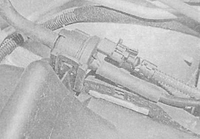
The purge valve is located on the right side of the engine compartment, behind the air cleaner.
1. Switch off ignition, wring out on a clamp and disconnect a contact socket of electroconducting of the valve.
2. Disconnect the hoses from the valve (try to remember the order from the connection), Release the clips, separate the valve from the air cleaner housing and remove it from the vehicle.
3. Installation is carried out in the reverse order.
Exhaust gas monitoring
Examination
Catalytic converter
Diagnostic equipment for checking the health of the catalytic converter is expensive and extremely difficult to operate. If you suspect a converter failure, drive the vehicle to a workshop for inspection.
Whenever the vehicle is lifted off the ground for any reason, inspect the transducer for signs of mechanical damage, signs of leakage, and corrosion. Check the condition of the welds and the tightness of the flange bolts securing the device to the sections of the exhaust system. A defective catalytic converter must be replaced.
Despite the reliability of the design of the converter, there is a fairly high probability of blockage. The simplest way to check the patency of the transducer is to check using a vacuum gauge.
1. Connect a vacuum gauge to the intake manifold vacuum source (see Repair procedures for diesel engines 1.7 l and 2.0 l without removing them from the car).
2. Warm up the engine to normal operating temperature, move the selector lever to the «R» (models with AT), or shift into neutral (models with manual transmission) and apply the parking brake.
3. Read the vacuum gauge readings with the engine idling.
4. Quickly open the throttle almost to the stop, then immediately release it, dropping the speed to idle. Read and record the vacuum gauge readings.
5. Repeat the described test three more times, each time recording the result.
6. If the result of the fourth measurement is more than 2.54 mm Hg. Art. lower than the reading taken at idle, therefore, there is a possibility of a violation of the transducer or muffler.
Lambda probe (oxygen sensor)
1. Locate the sensor's electrical connector. From the reverse side of the connector, insert an unfolded paper clip into the signal wire contact socket (terminal no. 1 []), insert the second paper clip into the socket of terminal No. 2 (weight). Connect the positive probe of the voltmeter to the first paper clip, connect the negative probe to the paper clip inserted into the ground terminal. Set the parking brake, move the AT selector lever to the position «R», on models with manual transmission, select neutral. Jack up the front of the car and place it on jack stands.
2. Start the engine and begin to monitor changes in the signal voltage of the lambda probe.
Try not to touch the heated surfaces of the exhaust system!
3. At the initial stage, the cold sensor should generate a constant signal with an amplitude of 0.1-0.2 V (open loop mode). After about two minutes, the engine will reach normal operating temperature and the sensor reading will begin to fluctuate between 0.1 and 0.9 V (closed loop mode). If the system does not transition to closed loop mode, or transitions with an unacceptably long delay (lazy sensor), replace the sensor.
4. Check up also serviceability of functioning of a heater of a lambda probe. Disconnect the probe wiring connector and connect an ohmmeter between the heater terminals (terminals No. 3 and 4). The nominal resistance is 10-40 ohms.
5. Check the power supply to the heater. Disconnect the electrical connector and measure the voltage on it from the side of the harness between terminal No. 4 and ground. With the ignition on (do not start the engine) The voltmeter should record the voltage of the battery. If there is no power, check the condition of the wiring in the circuit between the main relay, ECM and lambda probe.
6. At negative results of the above checks, replace the faulty sensor.
Replacement
Catalytic converter
The catalytic converter is a maintenance-free component, however, there are some points that the owner of a suitably equipped vehicle should pay attention to.
- Do not fill a car equipped with a catalytic converter with unleaded fuel - the lead contained in it is deposited on the surfaces of the catalyst coated with rare earth metals, which significantly reduces the efficiency of the converter and can eventually lead to its complete failure;
- Monitor the condition of the components of the exhaust system, regularly perform the necessary checks in accordance with the Vehicle Maintenance Schedule (see chapter Current service);
- If a misfire occurs, you should refuse to use the vehicle until the malfunction is eliminated - the unburned fuel that enters the converter can then ignite and cause the catalyst to fail;
- For the same reason, you should refuse to start the engine by towing or pushing the car;
- Do not turn off the ignition at high engine speeds;
- Do not use any fuel and engine oil additives - they may contain components that are harmful to the catalytic converter.
- If a bluish plume appears at the outlet of the exhaust gas system, which is the result of burnout of the engine oil, the compilers of this Guide also recommend refusing to operate the car (see point c);
- Remember that the catalytic converter operates at very high operating temperatures - do not park the car on areas covered with dry grass or last year's leaves;
- Remember that the catalytic converter can easily be damaged by impacts - be careful when doing any work near it;
- The smell of hydrogen sulfide (rotten eggs) in the first days of operation of a new car is a consequence of the normal functioning of the catalytic converter - the smell should disappear after the first few thousand kilometers;
- With a serviceable car, the service life of the catalytic converter is up to 150,000 km. In the event of a decrease in the efficiency of functioning, the catalytic converter must be replaced.
For a description of the removal and installation procedures for the catalytic converter, see Removal and installation of a final collector.
Lambda probe (oxygen sensor)
When servicing the lambda probe, some special precautions should be observed:
- The lambda probe is equipped with a piece of electrical wiring tightly built into it and equipped with a contact plug, attempts to disconnect which can lead to irreversible failure of the sensor;
- Try to keep the sensor louvers or its electrical connector free of dirt and grease;
- Do not use any solvents to clean the lambda probe;
- Handle the sensor with extreme care - do not drop it and try not to shake it off;
- The silicone protective cover must be put on the sensor in a strictly defined way so as not to be melted and not to interfere with the proper functioning of the probe.
Models with engines 1.4 and 1.6 l
1. Warm up the engine to normal operating temperature, shut off and disconnect the negative cable from the battery.
2. Walk along the wiring from the sensor screwed into the left side of the exhaust manifold to the connector of its wiring. Release the wiring from the clamps and disconnect the connector.
3. Turn out the gauge and remove it from a collector.
Try not to touch the heated elements of the exhaust system!
4. Installation is carried out in the reverse order. Before screwing in, lubricate the threaded part of the sensor with heat-resistant grease type Opel No. 1948602/90295397. Tighten the sensor with the required force and make sure that the electrical wiring is laid correctly - the harness should not touch the heated surfaces of the exhaust system.
Models with engines 1.8 and 2.0 l
1. Apply the parking brake, then jack up the front of the vehicle and place it on jack stands. Disconnect the negative cable from the battery.
2. Walk along the electrical wiring from the sensor screwed into the receiving section of the exhaust system to the connector of its electrical wiring on the left side of the cylinder head. Release the wiring from the clamps and disconnect the connector.
3. Unscrew the sensor and remove it from the car - the sealing ring must be replaced without fail.
4. Installation is carried out in the reverse order. Before screwing in, lubricate the threaded part of the sensor with heat-resistant grease type Opel No. 1948602/90295397. Tighten the sensor with the required force and make sure that the electrical wiring is laid correctly - the harness should not touch the heated surfaces of the exhaust system.
Exhaust gas recirculation system (EGR)
Examination
All models
An exhaustive system check can only be performed using specialized equipment connected to the DLC diagnostic connector (see The principle of operation of fuel injection systems). Failed EGR valves must be replaced.
Replacement
EGR valve
Petrol models
1. Turn off the ignition, disconnect the wiring from the valve. On models equipped with SOHC engine, the valve is installed in the middle part of the inlet pipeline, on models with DOHC engines - on the left side.
2. Turn out fixing screws and remove the valve in gathering with a sealing lining.
3. Installation is carried out in the reverse order. Do not forget to replace the gasket, make sure that the valve is tightened with the required force.
Diesel models
Models with 1.7L SOHC engines
1. Release the clamps, unscrew the support bracket mounting bolts and remove the boost pipe connecting the turbocharger to the intercooler.
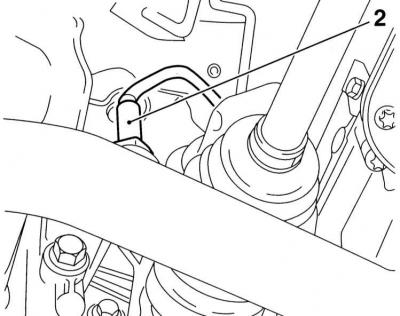
2. Disconnect the vacuum hose from the EGR valve, remove the retaining ring and remove the EGR valve from the left side of the intake manifold.
3. Installation is carried out in the reverse order.
Models with 1.7L DOHC engines
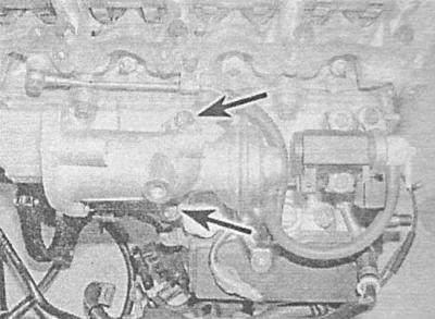
1. Remove the ECM (see The principle of operation of fuel injection systems). Remove the mounting bolts and remove the ECM support bracket located above the EGR valve.
2. Disconnect the vacuum tube from the EGR valve.
3. Turn out fixing bolts and disconnect an inlet tube from the top part of the EGR valve.
4. Loosen the EGR pipe connector on the valve with a wrench.
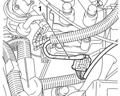
EGR valve (engine 1.7 l DOHC)
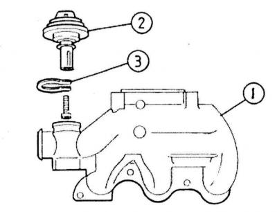
1 - Inlet pipeline
2 - EGR valve
3 - Retaining ring
5. Give bolts of fastening of the valve EGR to the inlet pipeline, - try to remember an adjusting position of the basic arms fixed by the same nuts.
6. A failed valve must be replaced.
7. Installation is carried out in the reverse order.
Models with 2.0L engines
The valve is not supplied individually to the aftermarket and in case of failure it is replaced as an assembly with the upper section of the inlet pipeline (see Removal and installation of the inlet pipeline).
EGR valve control solenoid valve - diesel models
Models with 1.7L SOHC engines
1. Disconnect the electrical wiring and vacuum hoses from the valve assembly at the rear of the intake manifold - try to remember the gasket and the order of connecting the lines.
2. Turn out two fixing bolts and remove the electromagnetic valve.
3. Installation is carried out in the reverse order.
Models with 1.7L DOHC engines
1. If necessary, remove the air cleaner and intake duct on the right side of the engine compartment (see Removal and installation of components of an inlet air path).
2. The valve is installed on the right side of the inlet pipeline. Disconnect the vacuum hoses from the valve - pay attention to the difference in their diameters.
3. Disconnect the electrical wiring from the valve.
4. Turn out two fixing bolts and remove the valve.
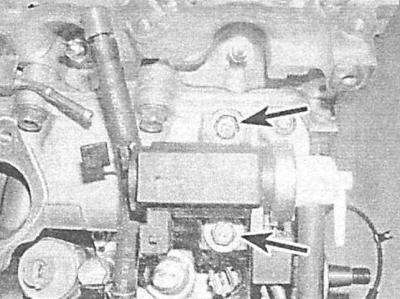
5. Installation is carried out in the reverse order.
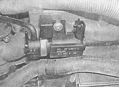
Models with 2.0L engines
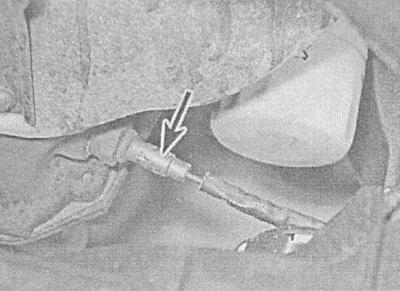
The valve is installed in the front left side of the engine compartment, adjacent to the pipeline changeover valve. Moreover, the EGR valve is the rear of the two and can be identified by the black color of the wiring.
1. Disconnect the electrical wiring and vacuum hoses from the valve. Unscrew the mounting screws and remove the valve from the support bracket - try to remember the installation position of the components.
2. Installation is carried out in the reverse order.
Visitor comments