
Models 1.7L SOHC
New pipe nuts are required during installation.
1. Disconnect the negative cable from the battery.
2. If necessary, remove the air cleaner housing and intake ducts with the MAF sensor (see Removal and installation of components of an inlet air path).
3. On right hand drive models remove generator (see chapter Engine electrical equipment).
4. Remove the exhaust manifold (see Removal and installation of a final collector).
5. Disconnect the electrical wiring from the boost pressure sensor mounted on the intake manifold.
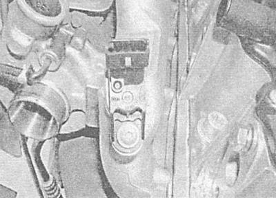
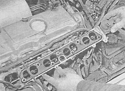
6. Give fixing nuts and remove the inlet pipeline from a head of cylinders together with a sealing lining.
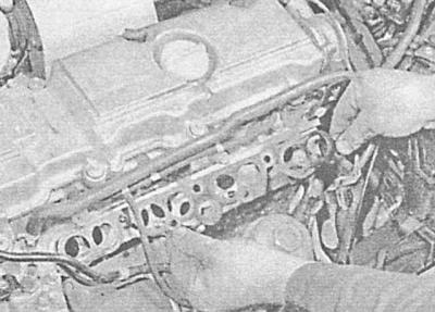
7. Make sure that the mating surfaces of the cylinder head and intake manifold are absolutely clean and dry, and install a new gasket on the pipeline studs.
8. Install the pipeline on the regular one and screw the nuts of its fastening. Tighten the nuts evenly in a diagonal sequence in several steps to the required torque.
9. Connect the electrical wiring to the boost sensor.
10. Make sure that the mating surfaces of the exhaust manifold and head are absolutely clean and dry. Install manifold (see Removal and installation of a final collector).
11. On right hand drive models install the generator (see chapter Engine electrical equipment).
12. Install intake ducts and air cleaner housing with MAF sensor (see Removal and installation of components of an inlet air path).
13. Connect the negative cable to the battery.
Models 1.7L DOHC
New pipe nuts are required during installation.
1. Disconnect the negative cable from the battery.
2. Lift up lock levers of clamps and disunite two contact sockets of electroconducting ECM.
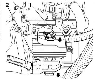
3. Give fixing nuts/bolts and remove ECM.
4. Release fixture and disconnect an inlet air line from a tube connecting the gauge MAF with a turbocharger.
5. Remove the bolts securing the boost tube support bracket to the left side of the timing case and the EGR valve.
6. Remove the bolts securing the EGR tube to the exhaust manifold and the left side of the timing case. Loosen the large union connector on the EGR valve and remove the tube.
7. Give union nuts and remove fuel tubes of atomizers. The compilers of this manual insist on releasing the bolt and shifting the oil cooler housing to the right (see chapter Engine) to ensure adequate access to the rear of the fuel pump, prepare to collect spilled fuel.
In no case do not bend the tubes - the internal pressure in them is very high!
8. Disconnect the electrical wiring and vacuum hoses from the EGR solenoid valve (see Systems of release and decrease in toxicity of the fulfilled gases)
9. Disconnect the boost pressure sensor wiring connector.
10. Release the wiring harness from the intermediate clamps on the inlet pipeline - try to remember the route of laying the braid.
11. Disconnect the fuel return pipe from the top of the intake manifold and high pressure fuel pump.
12. Turn out two fixing bolts and remove the EGR valve from the inlet pipeline.
13. Turn out fixing bolts and nuts and remove back (and, if necessary, the front) intake pipe section.
14. Thoroughly clean the mating surfaces of the head and pipeline and install a new gasket.
15. Further installation is carried out in the reverse order to the dismantling of the components. Make sure all fasteners are tightened evenly and to the correct torque.
16. Make sure that the fitting connectors are securely tightened (see Power and exhaust systems, Specifications), Finally, check them for signs of leak development.
Models 2.0 l
When installing, new nuts for fastening the lower section of the pipeline are required.
1. Disconnect the negative cable from the battery.
2. On low pressure turbocharged engines (X20DTL/Y20DTL) remove the metal tube and air duct connecting the intake manifold to the turbocharger. On high pressure engines (Y20DTH) remove the air duct connecting the pipeline to the intercooler.
3. Remove the screws securing the electrical wiring routing trough to the top of the intake manifold. Release the connector latches and disconnect the electrical wiring from the temperature sensors, injection pump, CKP sensor and boost pressure sensor.
4. Move the chute away from the pipeline.
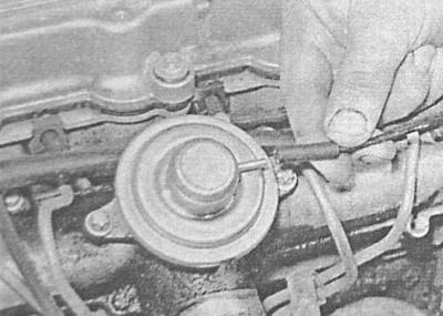
5. Disconnect the vacuum tube from the EGR valve on top of the intake manifold.
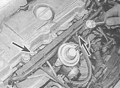
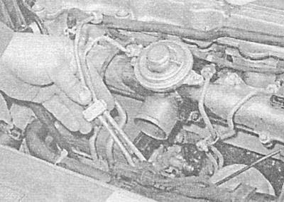
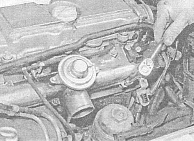
6. Thoroughly wipe the nipple connectors and disconnect the fuel pipes from the injectors and injection pump, - when loosening the nuts, hold the mating parts of the injection pump connectors with a second open-end wrench. Seal open ends of fuel lines and fittings immediately to minimize fuel loss and to prevent dirt from entering the fuel system.
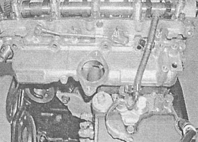
A - Loosening the union nut securing the fuel pipe to the injector and injection pump
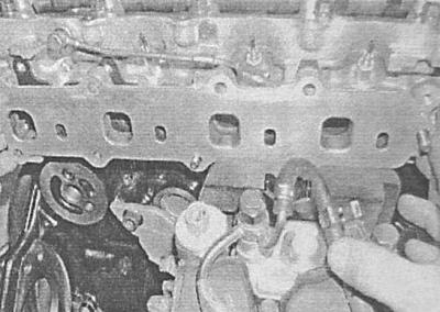
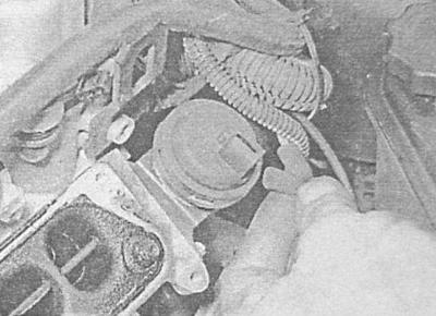
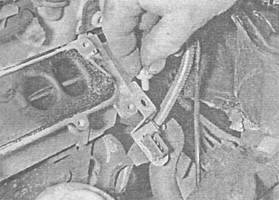
C - Removing fuel lines
A.
B.
7. Gradually and evenly loosening, unscrew the fixing bolts and carefully remove the upper part of the pipeline - the sealing gasket must be replaced without fail.
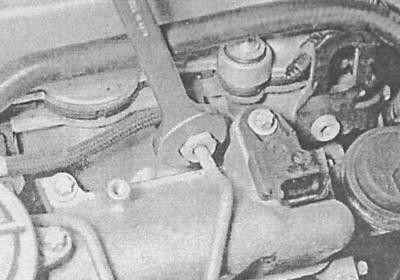
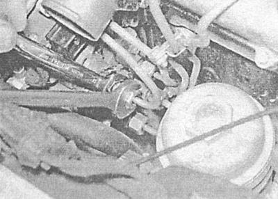
8. To remove the lower tubing section, disconnect the vacuum tube from the tubing changeover valve diaphragm assembly.
9. Turn out bolts of fastening to the pipeline of a basic arm of a socket of electroconducting.
10. Evenly and gradually loosening, give the fixing nuts and remove the lower section of the pipeline from the cylinder head - the sealing gasket must be replaced without fail.
11. Make sure that the mating surfaces are absolutely clean and dry.
12. Lay a new lining on a head of cylinders, then establish the lower section of the pipeline. Screw on the new fixing nuts and diagonally tighten them evenly in several steps to the required torque. Connect the switch valve hose and install the wiring support bracket.
13. Lay a new gasket over the top cut of the bottom section, and install the top section of tubing. Tighten the mounting bolts to the required torque.
14. Install the fuel pipes, - make sure that the nuts of the union connectors are tightened with the required force.
15. Install the electrical wiring routing trough on the pipeline, securely tighten the mounting bolts, and restore the original electrical wiring connection. Connect the vacuum tube to the EGR valve.
16. Install intake duct/pipe (see Removal and installation of components of an inlet air path). Establish on a head of cylinders a plastic protective casing.
17. Connect the negative wire to the battery.
Visitor comments