


Prevent dirt from entering the pump and fuel lines.
1.7L SOHC Models
1. Disconnect the negative cable from the battery.
2. Remove the pump drive gear (see Chapter Engine).
3. Unscrew the nuts of the union connections and remove the fuel pipes (see Removal and installation fuel injectors).
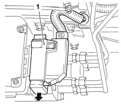
4. Release the lock (1) securing the fuel injection pump control module contact connector to the engine and disconnect the connector.
5. Thoroughly clean and mark the fuel lines to be disconnected. Remove the sealing rings from the union connectors, and seal the open ends of the pipes with suitable plugs immediately after disconnection.
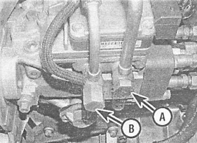
6. Remove the bolts securing the rear pump mounting bracket to the bracket on the cylinder block.
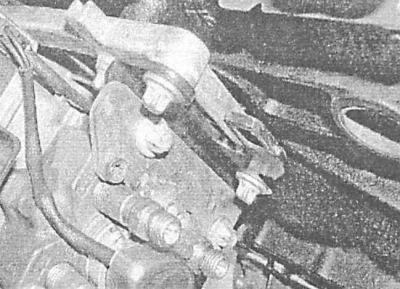
7. Remove the front mounting nuts and remove the pump from the engine.
Do not attempt to disassemble the fuel injection pump! If signs of malfunction of the pump appear, contact the car service specialists for advice.
8. Install the pump in its original place, screw in the front and rear mounting bolts and tighten them to the required torque.
9. Restore the original connection of the electrical wiring, ensure that the connector is securely fixed with the locking element - press the latter to the left of the vehicle.
10. Connect the fuel supply and return lines to the pump, tighten the union connections to the required torque.
11. Make sure that the fitting connectors are absolutely clean and dry and reconnect the fuel lines to the injection nozzles - make sure that the fitting connector nuts are tightened to the required torque.
12. Install the fuel injection pump gear wheel in place and tighten its mounting bolt by hand - it should still be possible to turn the wheel by hand.
13. Using an open-end wrench on the fastening nut, turn the pump mounting flange until its mark is aligned with the mark on the gear wheel and the stop drilling in the pump. Pass the Vauxhall KM-6011 device through the flange and insert it into the drilling, thereby fixing the pump assembly. If you do not have a special device at hand, you can use a piece of rod with a diameter of 9.5 mm and a length of 75 mm.
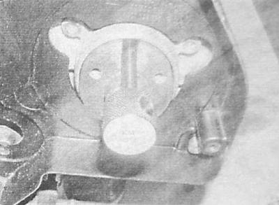
14. Install the timing belt (see Chapter Engine).
15. Further installation is carried out in the reverse order of dismantling the components. Please note the following points:
- Make sure all fasteners are tightened to the required torque;
- Make sure that the wiring is laid correctly and securely fastened; if necessary, replace the contact connectors;
- After starting the engine, check the nipple connections for signs of developing leaks.
Remember that starting the engine will take a little longer than usual, due to the need to automatically bleed the fuel system to remove air locks.
Models 1.7L DOHC
1. Disconnect the negative cable from the battery.
2. Remove the pump drive gear (see Chapter Engine).
3. Remove the intake manifold (see Removal and installation the intake manifold).
4. Remove the fuel injection pump control module (see Removal and installation of electrical components of the power supply system).
5. Disconnect the electrical wiring and two vacuum pipes, unscrew the two mounting bolts and remove the boost pressure control solenoid valve (see Removal and installation of electrical components of the power supply system).
6. Disconnect the electrical wiring from the atmospheric pressure sensor, remove the sensor from the mounting support bracket (see Removal and installation of electrical components of the power supply system). Unscrew the two mounting bolts and remove the bracket. Remove the fuel injection pump control module mounting bracket.
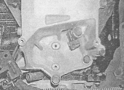
7. Disconnect the fuel supply and return lines from the pump.
8. Pull off the high-pressure fuel pump insulation, disconnect the contact connectors of the information sensors on the pump, release the harnesses from the intermediate clamps - try to remember the order of wiring.
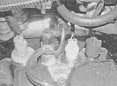
9. Unscrew the two fastening nuts and remove the high-pressure fuel pump from the valve timing housing. Remove the sponge insulation laid between the pump and the cylinder block.
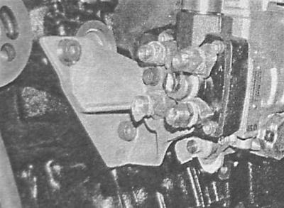
Do not attempt to disassemble the fuel injection pump under any circumstances; if necessary, seek help from car service specialists.
10. Place a new sponge seal between the pump and the cylinder block, achieve the required engagement of the pump shaft with the valve timing mechanism, then screw on two new mounting nuts - at this stage tighten the nuts only by hand.
11. Install the fuel injection pump support bracket to the cylinder block, screw in the mounting bolts and tighten them to the required torque. Only tighten the bracket-to-pump mounting bolts by hand for now. Place foam insulation around the pump. Before installing the rear section, connect the wiring to the pump memory module (PROM) on the side of the assembly.
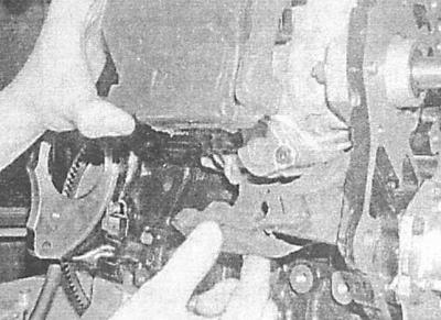
12. Reinstall the pump drive gear (see Chapter Engine).
13. Install the timing belt (see Chapter Engine).
14. Perform the injection timing setting procedures (see Checking and adjusting fuel injection timing settings).
15. Further installation is carried out in the reverse order of dismantling the components. Please note the following points:
- Make sure all fasteners are tightened to the required torque.
- Make sure that the wiring is laid correctly and securely fastened; if necessary, replace the contact connectors.
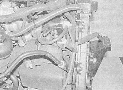
- After starting the engine, check the nipple connections for signs of developing leaks.
Remember that starting the engine will take a little longer than usual, due to the need to automatically bleed the fuel system to remove air locks.
2.0 liter models
Since dismantling the pump involves the need to remove the upper timing chain and sprockets, installation will require special Opel tools or self-made analogues to ensure correct installation, without which the installation of valve timing is not possible (see Chapter Engine). If there is no possibility to use special tools, ask for help from car service specialists. If due to circumstances the pump has to be removed without using special tools, first mark the relative position of the sprockets and flanges. It would not be superfluous to purchase a special head MKM-604-30, which will be needed to unscrew the front bolts of the fuel injection pump.
When installing, you will need a new camshaft sprocket mounting bolt and upper chain guide mounting bolts.
1. Remove the intake manifold (see Removal and installation the intake manifold).
2. Thoroughly wipe the surfaces around the fittings, then unscrew the bolts, remove the sealing washers, disconnect and move aside the fuel supply and return lines.
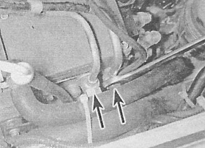
3. Remove the upper timing chain and sprockets.
4. Through the holes in the lower chain sprocket, unscrew the front bolts (1) securing the high-pressure fuel pump.
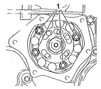
5. Unscrew the mounting bolts and remove the pump mounting bracket.
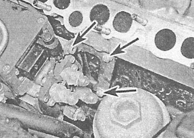
6. Remove the pump from the mounting seat together with the sealing ring. During assembly, the ring must be replaced without fail.
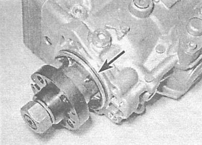
Do not attempt to disassemble the fuel injection pump under any circumstances; if necessary, seek help from car service specialists.
7. Before installation, make sure that the mark on the pump flange is correctly aligned with the fixing hole in the housing. Check the correct position of the crankshaft and camshaft.
8. Install the pump in place, making sure that the sprocket is correctly aligned with the pump flange. Screw in the front pump mounting bolts and tighten them to the required torque.
9. Install the support bracket onto the rear of the pump and tighten its mounting bolts to the required torque.
10. Install the upper timing chain and sprockets (see Chapter Engine).
11. Install new sealing washers on both sides of the fuel supply and return line union connections, screw in the union bolts and tighten them to the required torque.
12. Install the intake manifold (see Removal and installation the intake manifold).
13. Connect the negative cable to the battery and start the engine.
Visitor comments