
Attention: Do not allow dirt to enter the pump and fuel lines!
Z13DT engine
1. On this engine, the injection pump is installed on top of the engine, next to the vacuum pump (see resist. illustration), and is driven by the exhaust camshaft.
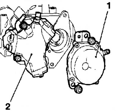
18.1. Vacuum pump (1) and injection pump (2) Z13DT engines are mounted on the camshaft housing
2. Remove the fuel filter (see chapter 1) and disconnect all supply fuel lines and electrical wiring from it, remove the filter clamp (see Section 9).
3. Disconnect the vacuum line, turn out 2 bolts and remove the vacuum pump.
Note: The vacuum pump is driven by the distributor inlet camshaft.
4. Disconnect all fuel lines, remove 3 bolts and remove high pressure fuel pump.
5. Installation is made in an order, the return to an order of removal. It is necessary that when installing the injection pump, the adaptive plate (see resist. illustration) its drive got into the groove of the camshaft.
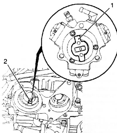
18.5. Adaptive plate (1) injection pump drive (Z13DTH engine): 2. Camshaft groove
Z17DT engines (H/L)
6. On these models, the injection pump is installed on the left (viewed from the timing side) side of the engine block. The injection pump is driven by a toothed belt.
7. Remove the toothed belt (see chapter 2). Using the special tool KM-6099, remove the pump drive gear (see resist. illustration).
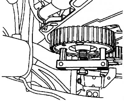
18.7. Removing the gear wheel of the injection pump drive using the KM-6099 tool (on the example of the Z17DTH engine)
8. Disconnect the fuel lines from the injection pump assembly, as well as other supply lines and wiring harnesses that block access to the injection pump.
9. Loosen the 2 nuts and remove the injection pump from the engine.
Note: If there is not enough space to remove the injection pump from the guide pins, remove the starter (see chapter 5).
10. Installation is carried out in the reverse order.
Visitor comments