
General information
1. Even at the dawn of the automotive industry, when designing internal combustion engines, the dependence of the combustion efficiency and, accordingly, the return of the internal energy of the working mixture on the proportion of fuel and air in its composition was revealed. For the most efficient operation, a strictly defined proportion is required, which must be maintained in all engine operating modes. This, in turn, leads to fuel economy.
2. It is especially important to maintain this proportion for gasoline engines. To date, all gasoline engines of leading automotive manufacturers are equipped with an electronically controlled injection system.
3. With this method of mixture formation, the air necessary for fuel combustion enters through the air filter and through the throttle valve into the intake manifold. The amount of incoming air is determined by the corresponding sensor.
4. Fuel is sucked from the fuel tank by the electric pump, passed through the fuel filter and fed into the fuel distribution line. Through the injectors, fuel is injected into the intake manifold located in front of the intake valves of the cylinders, where it mixes with the air stream.
5. The engine control module, observing the ignition sequence, regulates the opening time of the injector channels and thereby the amount of injected fuel depending on the amount of air and engine load. In addition, the ECM controls the throttle valve, adjusting the amount of air supplied if necessary.
6. Initially, to determine the amount of fuel supplied to the engine cylinders, only the incoming air flow was measured. But gradually, new dependencies were identified that affect the efficiency of fuel combustion, and the requirements for exhaust gas toxicity were also tightened, which led to the complication of engine control systems.
7. Modern fuel injection control systems are a complex set of sensors, control units, actuators and electronic circuits (see resist. illustrations). Below is a description of the principles of operation of some of them:
- The gas pedal position sensor is built into the pedal assembly. From sensor to engine control module (ECM) an appropriate electrical signal arrives, setting the values of the required mode of vehicle movement;
- The throttle control module contains the actuator (stepper motor) and damper potentiometer. The electric motor regulates the position of the throttle valve and allows you to maintain a constant idle speed, regardless of the connection of additional consumers. The potentiometer sends information to the ECM about the current value of the throttle angle;
- The camshaft position sensor provides the ECM with information about the ignition timing in the first cylinder of the engine to synchronize the ignition timing and injection sequence in other cylinders;
- A thin sensor plate is installed in the body of the air mass measurement sensor, through which an electric current is passed. Due to the passing air flow, the plate is cooled. The control unit regulates the heating current so that the temperature of the plate remains constant. Fluctuating amperage during heating allows the ECM to determine the engine load condition and adjust the amount of fuel injected accordingly.
- The coolant temperature sensor is installed in the thermostat housing (see chapter 3). It is an NTC resistor - as the temperature of the coolant rises, its resistance decreases and the corresponding signal is sent to the ECM;
- The knock sensor is mounted under the exhaust manifold in the cylinder block. It sets the ignition moment at the boundary of the start of detonation combustion of the fuel, thereby, on the one hand, preventing the process of detonation combustion of the fuel mixture, and on the other hand, ensuring the most complete combustion of the fuel and reducing its consumption;
- The lambda probe allows you to monitor the composition of the working mixture by measuring the residual oxygen in the exhaust gases. As a result of the measurement, a certain voltage is created on the sensitive element of the lambda probe, by the value of which the ECM determines the need to change the composition of the fuel mixture. The Corsa C/Meriva models are equipped with two oxygen sensors, pre-catalytic and post-catalytic.
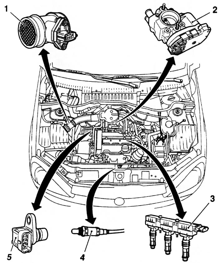
12.7a. Some sensors and modules of the gasoline engine management system (on the example of the Z1 OXE engine (R)): 1. Air mass measurement sensor; 2. Throttle control module; 3. Ignition module; 4. Precatalytic lambda probe; 5. Camshaft position sensor
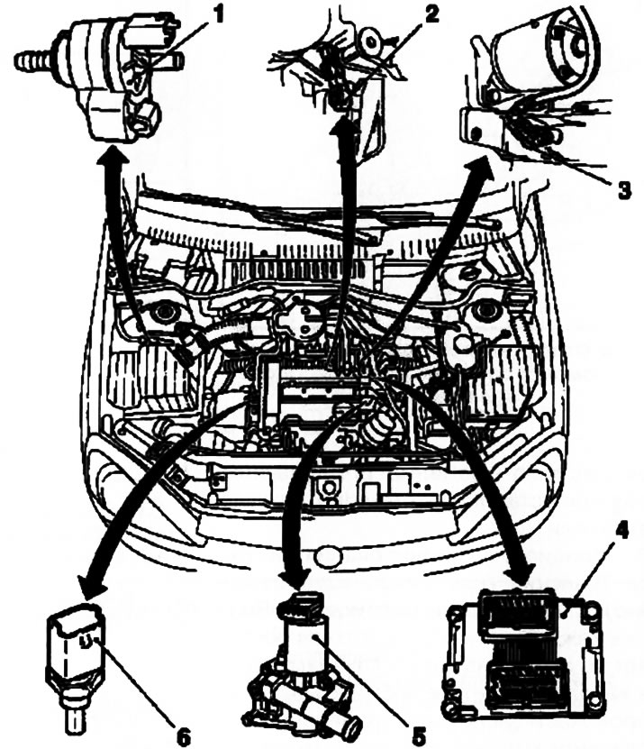
127b. Some sensors and modules of the gasoline engine management system (on the example of the Z1 OXE engine (R)): 1. EVAP system valve; 2. Knock sensor; 3. Crankshaft position sensor; 4. Electronic engine control module (ECM); 5. Exhaust gas regeneration valve; 6. Coolant temperature sensor
8. Different systems may differ from each other in the number of elements involved, depending on the design of the power unit and the requirements for a particular engine. Independent intervention in the adjustment and configuration of these systems is not allowed. For this, special diagnostic and adjustment devices are used, which are available, as a rule, only at specialized service stations.
Twinport system (engines Z10XEP/Z12XEP/Z14XEP)
9. The models described in this manual may be equipped with twinport engines. This system is designed to increase the fuel efficiency of the engine and reduce the toxicity of exhaust gases when the engine is running at low speeds and idling. This system especially justifies itself when installed on small engines.
10. The principle of operation of the Twinport system (see resist. illustration) is as follows: Air enters each cylinder of the engine through two air channels. One of the channels can be blocked by an adjusting damper, the position of which is controlled by a drive rod from the vacuum regulator. When the channel is blocked by a damper, a vortex flow of the air-fuel mixture is created, which allows using lean mixtures at low engine loads and when it is idling, as well as increasing the percentage of exhaust gases entering through the recirculation system (EGR). This reduces the overall fuel consumption and reduces the content of harmful substances in the exhaust gases.
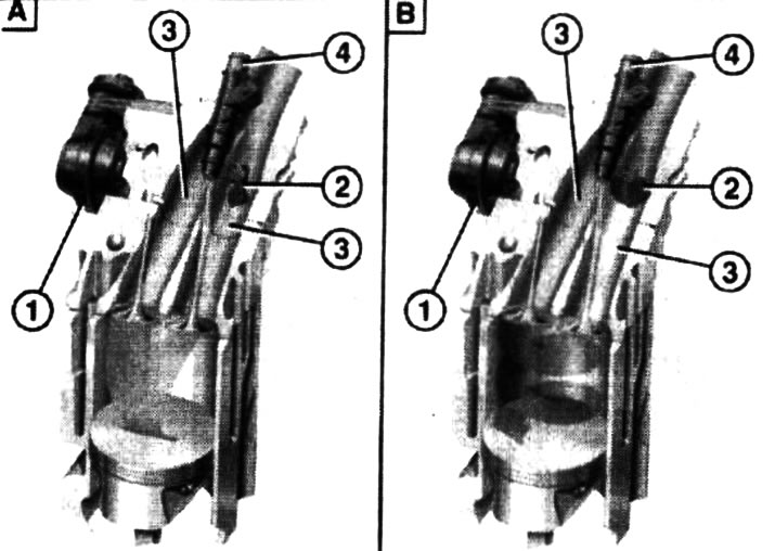
12.10. The principle of operation of the Twinport system: A. Regulating damper open (at full load); B. Control flap closed (when the engine is running at idle and when the car is stopped); 1, 2. Air-fuel mixture flow direction; 3. Inlet channels; 4. Vacuum regulator; 5. Injector; 6. Adjusting damper
Visitor comments