
Attention: Do not allow dirt to enter the pump and fuel lines!
Z19DT engines (H)
1. Disconnect a wire from the negative plug of the storage battery.
2. Remove the toothed belt.
3. Disconnect the supply lines from the fuel pressure pulsation damper (see resist. illustration) unscrew 2 bolts and remove it.
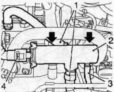
18.3 Fuel pressure pulsation damper (2) (Z19DTH engine) the arrows indicate the installation locations of the mounting bolts: 1. Fuel supply hoses; 3. Mass supply line; 4. Fuel return hose
4. Remove the bolt securing the gear wheel of the injection pump drive, keeping the wheel from turning with the help of special tools KM6347 and KM-956-1
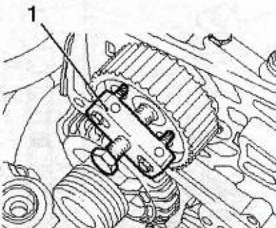
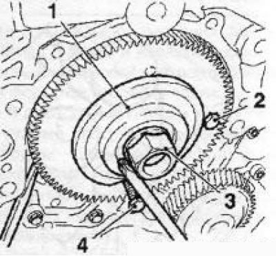
18.5 Fixture EN-46790 (1) for removing the gear wheel of the injection pump drive (Z19DTH engine)
5. With a special tool (see resist. illustration) press the wheel off the injection pump shaft, if necessary, use the help of an assistant.
6. Disconnect the fuel pipes from the injection pump assembly, loosen the 3 fixing nuts and remove the injection pump housing.
7. Installation is carried out in the reverse order.
Y20DTH/Y22DTR engines
8. Operations for removing/installing the injection pump on these engines are performed only on the removed engine, and therefore their description is not given in this Manual.
Y30DT engine
9. The injection pump is installed in the collapse of the cylinder block on the timing side.
To free access to it, it is necessary to dismantle all lines and nodes located above the collapse of the block. During these operations (not described here) you will have to remove a lot of small parts and lines - if necessary, it is recommended to contact the Opel service station.
10. Remove the bottom cover and two timing gears (see Chapter 2, Section 8).
11. Install special tool (see resist. illustration) screw the nut until it stops, unscrew the locking bolt (M6) loosen the nut and remove the injection pump outer gear. Remove the spring.
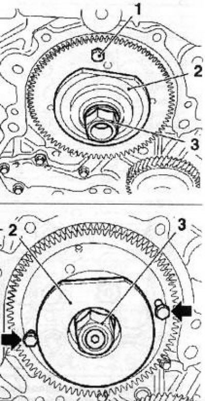
18.11 Installing the KM6376 tool (2) (Y30DT engine) - the arrows indicate the bolts for removing the internal gear of the injection pump 1 Locking bolt: 3. Fixture nut
12. Reinstall the KM-6376 tool (see illustration 18.11) screw 2 bolts into the holes of the internal gear (M6), position the gear so that the bolt on the right (looking at the gear) the parties were in position «for 2 hours», and the left bolt - «for 8 hours». Slowly screw in the left and right bolts and compress the injection pump inner gear.
13. Disconnect the electrical wiring, unscrew the 4 fixing bolts (see resist. illustration) and remove the injection pump housing.
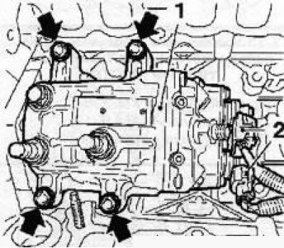
18.13 Bolts (indicated by arrows) mounting connector (2) electrical wiring injection pump (1) (Y30DT engine)
14. Installation is carried out in the reverse order of removal. The same tool is used to install the injection pump gears. Secure the outer gear against turning with a screwdriver (see resist. illustration), start one bolt first (M6) to hold the gear, press the fixture with a suitable tool (e.g. with a second screwdriver) and screw the second bolt - use the help of an assistant.
18.14 Installing the external drive gear of the injection pump (Y30DT engine): 1. Adaptation KM-6376; 2, 4. Pinion holding bolts (M6); 3. Fixture nut
Visitor comments