
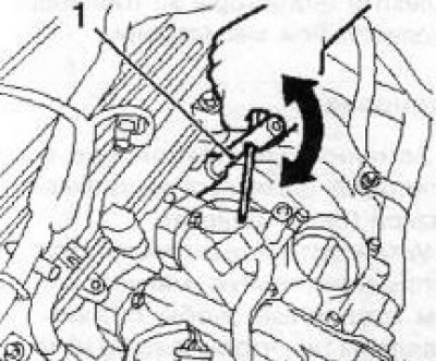
14.1a Install the KM6360 tool (1) and, by gently turning the injector, loosen its fit in the cylinder head seal (Z22YH engine)
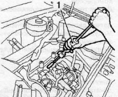
14.1b Using the KM-328-B tool (1) remove the injector from the cylinder head (Z22YH engine)
Removing
2. Disconnect the wire from the negative battery terminal and remove the engine cover.
3. Disconnect and remove the intake duct from the air cleaner to the throttle assembly and relieve the pressure in the fuel system.
4. Raise the car on a lift and disconnect the wiring connectors of the following sensors and devices:
- Post-catalytic lambda probe;
- Engine oil pressure sensor;
- crankshaft position sensor;
- Oil level sensor;
5. Lower the vehicle onto its wheels.
6. Disconnect the camshaft position sensor wiring connector and disconnect the cable «masses» from the generator.
7. Disconnect the fuel line from the fuel distribution line using the special tool Hazet 4501-1 (see resist. illustration). When disconnecting the line, cover the connector with a rag to prevent splashing of fuel, then close the fuel hose with a plug and lay it aside.
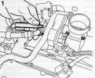
14.7 Disconnecting the fuel line using a special tool (1)
8. Disconnect the wiring connectors of the following sensors and devices:
- Compressor;
- Coolant temperature sensor;
- Air conditioning pressure sensor;
- Throttle control module;
- Engine control module (ECM);
- Knock sensor;
- ignition module;
- injection injector;
- Precatalytic lambda probe.
9. Turn out 2 fixing bolts (see resist. illustration) and remove the fuel distribution line along with the injectors from the engine.
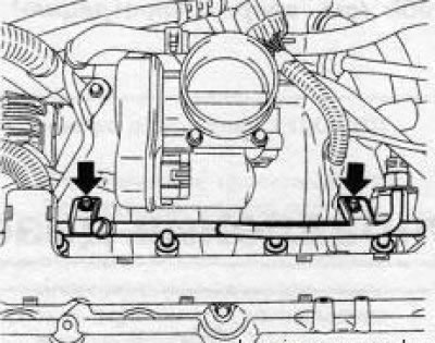
14.9 Bolts (indicated by arrows) mounts
10. Remove the retaining clips one by one (see resist. illustration) and remove the injectors from the fuel distribution line.
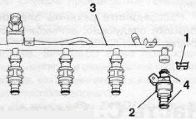
14.10 Attaching the injectors (2) to fuel rail (3): 1. Locking bracket; 4. Gaskets
Installation
11. Replace the O-rings of the injectors and lubricate them with silicone grease (white color).
12. Install the injectors on the fuel distribution line, while the locking brackets must be inserted so that the protrusion on the injector falls into the groove of the bracket (see resist. illustration).
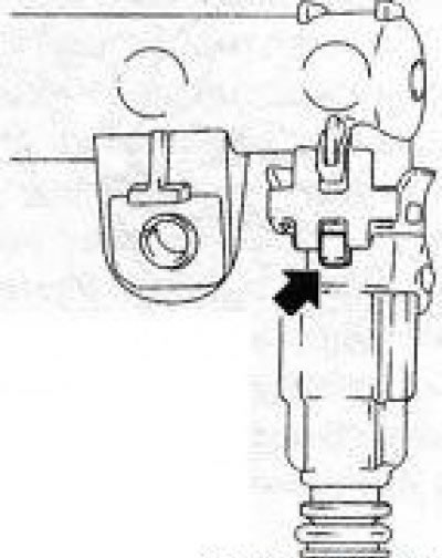
14.12 Installing the retaining clip
13. Establish a fuel-distributing highway and tighten its fastening with the demanded effort.
14. Further installation is carried out in the reverse order of removal.
Visitor comments