
OpelBook.ru
Cars AvtoVAZ Cars Mitsubishi Cars BMW Cars Mercedes Cars Nissan Cars Toyota Cars Chevrolet
English Русский
Български
Беларускі
Український
Српски
Hrvatski
Română
Polski
Slovenský
Magyar
 |  Sitemap  |  Contacts  |    


Main Astra Corsa Insignia Kadett Omega Vectra Zafira Others Articles
Vectra A (1988-1995, petrol) Vectra A (1988-1995) Vectra B (1995-2002, petrol) Vectra B (1995-2002) Vectra C (2002-2008)
  • Main
  • Vectra
  • Vectra C
  • Power unit
  • Power and control system
  • The operating principle of diesel engine fuel injection systems

The operating principle of diesel engine fuel injection systems (Opel Vectra C)

            0

When a diesel engine is running, clean air is sucked into its cylinders and compressed to high pressure. The air temperature rises to 600'C, which exceeds the ignition temperature of diesel fuel. Fuel is injected into the cylinder a little ahead of time and ignites. Thus, spark plugs are not used to ignite the fuel. When operating the vehicle in conditions of low outside air temperatures, the air temperature inside the cylinders after compression may be insufficient for the fuel to ignite spontaneously. In this case, it is necessary to preheat the incoming air flow. For this purpose, glow plugs are installed in the combustion chambers, heating them to the required temperature. The duration of preheating depends on the outside air temperature and is regulated by the engine management system via a preheating relay. When the glow plugs are activated, the corresponding indicator lamp lights up on the instrument panel.

5. There are three fuel injection methods for diesel engines: swirl injection, pre-chamber injection and direct injection.

6. In the swirl-chamber and pre-chamber methods, fuel is injected into the pre-chamber (fort chamber) the corresponding cylinder where it mixes with air and creates a ready working mixture, while part of the fuel immediately ignites and burns. Due to the swirls of the air flow and heating during combustion of part of the fuel, the working mixture becomes more homogeneous and heated. This ensures complete combustion of the fuel when it enters the cylinder and "softer" engine operation. The main disadvantage of these injection methods is the complication of the engine design. Direct injection continues to be the most common and most economical.


7. With direct injection, fuel enters directly into the combustion chamber through the nozzle atomizer. Each atomizer usually has 4-6 very fine holes drilled at different angles, through which fuel is sprayed in specially specified directions. Usually, there is a swirl chamber in the piston crown. Swirl chambers can have different shapes, which correspond to the directions of fuel spraying, promote better mixture formation and more efficient combustion of the working mixture. This method is used on all diesel engines discussed in this Manual.

8. On Y20DTH/Y22DTR engines, fuel is sucked from the fuel tank by a high-pressure fuel pump (HPFP). The HPFP creates the high pressure required for injection (about 900 bar) pressure and supplies fuel through the injectors to the engine cylinders in the order of cylinder operation. First, a preliminary injection of a small amount of fuel is performed, which, burning, prepares the conditions for the injection of the main portion of fuel. Due to this, a "softer" and more uniform combustion of fuel occurs, as in engines with a swirl-chamber injection method.

9. On Z19DT(H) engines, fuel is sucked from the fuel tank by an electric fuel pump and supplied to the high-pressure fuel pump (HPFP). For direct injection, these models use the "Common Rail" - common fuel distribution line for all cylinders (see accompanying illustration). This system frees the injection pump from the function of fuel distribution, which allows the pump to create a higher (approximately 1600 bar) pressure, - this promotes very fine atomization of fuel, due to which the process of mixture formation in the cylinders improves and the efficiency of combustion of the working mixture increases. Fuel distribution line (Common Rail) it is designed as a manifold, from which fuel is supplied to individual injectors.
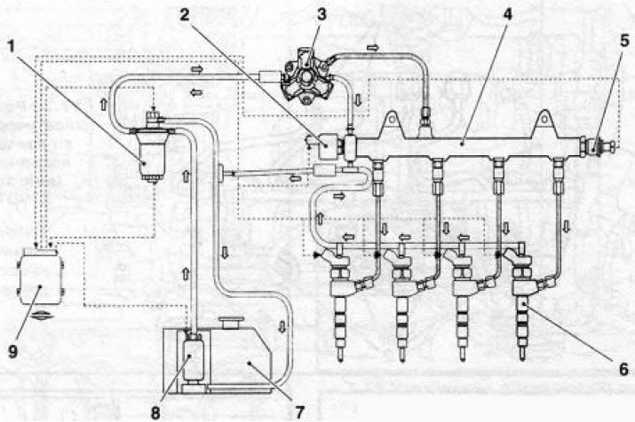


16.9 Common Rail injection system (using Z19DT(H) engines as an example):

16.9 Common Rail injection system (using Z19DT(H) engines as an example):

1. Fuel filter; 2. Pressure regulator; 3. High pressure fuel pump; 4. Fuel distribution line (Common-Rail); 5. Pressure sensor; 6. Nozzle; 7. Fuel tank; 8. Electric fuel pump; 9. Electronic module of the engine management system: dotted arrows indicate the direction of electrical signals, short arrows indicate the direction of fuel flow


10. On the 6-cylinder Y30DT engine, direct injection is also carried out through the Common-Rail system, but the fuel from the fuel tank is sucked in by the high-pressure fuel pump. The fuel injection pump of this engine is driven by the crankshaft via a gear mechanism.

11. On all engines, before the fuel enters the high-pressure fuel pump, it is cleaned in the fuel filter from dirt and water. The engine is equipped with injectors with electromagnetic control elements that receive signals from the engine management system, which regulates the amount of fuel supplied to the cylinder.

12. The high-pressure fuel pump does not require any special maintenance work. All moving elements of the fuel system are lubricated with diesel fuel.


This article is available at russian, bulgarian, belarusian, ukrainian, serbian, croatian, romanian, polish, slovak, hungarian
Checking the article: Meshcheryakov Damir

Share information:

Previous articles
Opel Vectra C: Power and control system
Next articles

Diesel Engine Control System
Removal and installation of fuel injectors
The operating principle of fuel injection systems of gasoline engines
Gasoline Engine Management System
Removal and installation the fuel tank ventilation system (EVAP) valve (gasoline)
Removal and installation the fuel tank
Removal and installation fuel injectors
Removal and installation of fuel injection pump
Turbocharger and Intercooler — General Information
Particulate filter (engines with a working volume of 1.9 l)
Exhaust gas system
Removal and installation of the exhaust system


See similar ones from other Opel car manuals:
▶ The operating principle of fuel injection systems Opel Astra G (1998-2004)
▶ The operating principle of fuel injection systems Opel Corsa B (1993-2000)
▶ Diesel Engine — Operating Principle Opel Ascona C (1981-1988)
▶ Fuel tank for diesel engine modifications Opel Insignia A (2008-2017)
▶ Fuel system of diesel engine Opel Omega A (1986-1993)
Link to this page in different formats

Visitor comments


No comments yet


How much will 46 + 26 =


Vectra C (2002-2008) 
  • General information
  • User manual
  • Vehicle device
  • Maintenance
  • Troubleshooting
  • Power unit
  • Engine repair
  • Cooling system
  • Power and control system
  • Engine electrics
  • Transmission
  • Clutch
  • Car gearbox
  • Drive shafts
  • Chassis
  • Car suspension
  • Steering
  • Brake system
  • Body
  • Exterior
  • Interior
  • Doors, locks and windows
  • Heating and ventilation
  • Electrical equipment
  • Equipment and devices
  • Headlights and lighting
  • Electrical circuits
Vectra B (1995-2002) 
  • General information
  • User manual
  • Weekly checks
  • Maintenance (gasoline)
  • Maintenance (diesel)
  • Troubleshooting
  • Power unit
  • SOHC gasoline engine
  • DOHC petrol engine
  • Diesel engine 1.7 liter
  • Diesel engine 2.0 liters
  • Engine repair
  • Cooling system
  • Fuel system (gasoline)
  • Fuel system (diesel)
  • Charging system
  • Launch system
  • Ignition and preheat
  • Transmission
  • Clutch
  • Mechanical gearbox
  • Automatic gearbox
  • Drive shafts
  • Chassis
  • Brake system
  • Wheel suspension
  • Steering
  • Body
  • Exterior
  • Interior
  • Doors and windows
  • Heating and ventilation
  • Electrical equipment
  • Equipment and devices
  • Electrical circuits
Vectra B (1995-2002, petrol) 
  • General information
  • Maintenance
  • Help with malfunctions
  • Power unit
  • Engine repair
  • Exhaust system
  • Cooling system
  • Fuel system
  • Multec injection system
  • Four point injection
  • Transmission
  • Clutch
  • Gearbox and drive
  • Chassis
  • Wheel suspension
  • Steering
  • Brake system
  • Wheels and tires
  • Body
  • Exterior
  • Interior
  • Electrical equipment
  • Fuses and electronics
  • Power devices
  • Ignition system
  • Lighting and signaling
  • Equipment and devices
  • Heating and ventilation
  • Electrical circuits
Vectra A (1988-1995) 
  • Power unit
  • Engine repair
  • Ignition system
  • Lubrication system
  • Cooling system
  • Injection system
  • Fuel system (carburetor)
  • Fuel system (diesel)
  • Exhaust system
  • Transmission
  • Clutch
  • Car gearbox
  • Chassis
  • Front suspension
  • Rear suspension
  • Steering
  • Brake system
  • Wheels and tires
  • Body
  • Exterior
  • Interior
  • Electrical equipment
  • Electrical circuits
Vectra A (1988-1995, petrol) 
  • General information
  • User manual
  • Maintenance
  • Power unit
  • SOHC engine
  • DOHC engine
  • Cooling and ventilation
  • Fuel system (carburetor)
  • Fuel system (injector)
  • Exhaust converter
  • Transmission
  • Clutch
  • Mechanical gearbox
  • Automatic gearbox
  • Drive shafts
  • Chassis
  • Brake system
  • Car suspension
  • Steering
  • Body
  • Body elements
  • Electrical equipment
  • Power devices
  • Equipment and devices
  • Electrical circuits
OpelBook.ru © 2017–2026 · Mobile version · · Sitemap: EN BG BY UA RS HR RO PL SK HU · Feedback · Site search
Astra F, petrol · Astra G, petrol · Astra G · Astra H · Astra J, petrol · Corsa B · Corsa C, petrol · Corsa C · Insignia A · Kadett D · Kadett E · Omega A · Omega B · Omega B2 · Vectra A, petrol · Vectra A · Vectra B, petrol · Vectra B · Vectra C · Zafira A, petrol · Frontera A, petrol · Frontera B · Ascona C · Vivaro A ·
We want your visit to be comfortable 🤝! We use cookies 🍪 to make that happen.