
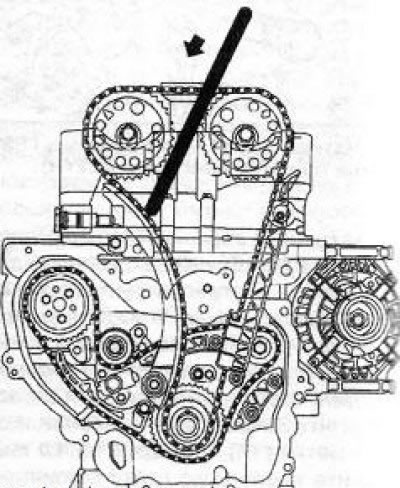
Z20NET/ 22SE/Z22YH petrol engines are equipped with two single row chains. One of them serves to drive the timing, the second chain drives 2 compensator shafts and the water pump of the cooling system.
On diesel engines Y20DTH / Y22DTR, the injection pump is driven by a two-row chain. Further from the fuel pump, the torque is transmitted to the camshaft sprocket through a single-row roller chain.
Checking and replacing the toothed belt must be carried out in strict accordance with the Maintenance Schedule. Whistling and howling of the toothed belt during engine operation indicate its excessively high tension, with low tension the belt hits the cover. It is recommended to replace the belt each time it is removed from the engine. If you plan to reuse the belt, mark with a marker before removing it from the gears (in the form of an arrow) to determine the direction of rotation during subsequent installation.
Note: The belt rotates clockwise when looking at the engine from the belt drive side.
Before removing the belt, it is recommended to draw a diagram of its tension. The chain requires virtually no maintenance during its entire service life. When troubleshooting or replacing chain driven units, it may be necessary to remove and sometimes replace the chain. After each removal of the chain, the valve timing must be adjusted. These operations can only be performed with the help of special tools, take care of purchasing them in advance.
During operation, as a result of weakening the belt / chain, increasing the length, or with some damage to the belt, he / she can jump one or more teeth on the gears / camshaft sprockets, which will lead to a violation of the valve timing, a decrease in engine efficiency, and in in some cases to failure of valves or pistons of cylinders. The valve timing is adjusted with the toothed belt / chain removed by aligning the marks / installing devices when setting the TDC position for the corresponding piston.
Attention! When turning the camshafts with the toothed belt/chain removed, none of the pistons should be in the TDC position - otherwise the valves will rest against the piston, which can damage the valves and / or pistons. It is necessary to turn the crankshaft of the engine approximately 60' from the TDC position! The crankshaft can be left unturned if only slight displacement of the camshafts is required - while choosing the shortest path to the TDC position.
Note: After replacing the toothed belt, it is recommended to stick a label on the top timing case cover indicating the current mileage and the date of replacement.
Attention! Before starting work on removing the toothed belt / chain, do not forget to disconnect the cable from the negative terminal of the battery!
Engines Z16XE/Z18XE
Removing
1. Remove the engine top cover.
2. Remove the air cleaner and right front wheel.
3. Remove the multirib belt.
4. Remove the locking pin and loosen the multirib belt tensioner. Remove the fixing bolt (see illustration) and remove the device from the engine.
8.4 Remove the locking rod to remove the tensioner (2) and remove the fixing screw (engines Z16XE/Z18XE)
5. Set the piston of the first cylinder to the TDC position of the compression stroke.
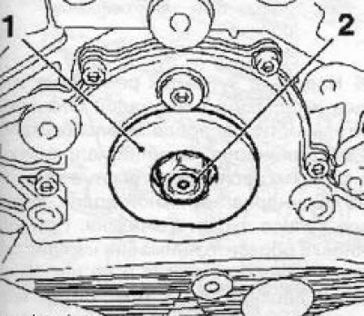
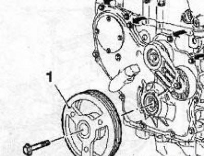
6. Remove the crankshaft pulley (see Section 5), then reinstall the fixing bolt and secure the timing belt drive wheel with it.
7. Turn out a fixing bolt (see resist. illustration) and remove the lower timing cover.
8.7 The arrow indicates the bolt for fastening the lower timing cover (engines Z16XE/Z18XE)
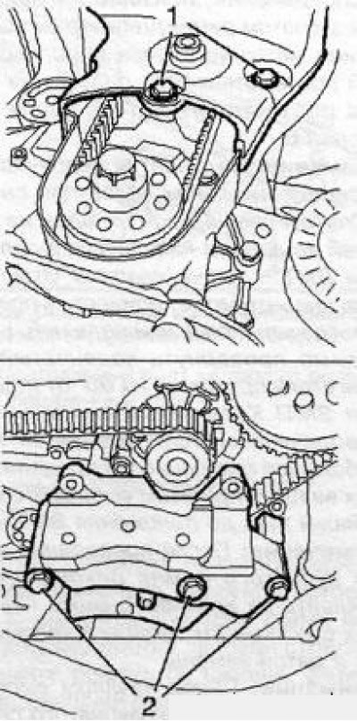
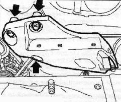
8. Remove the right engine mount.
9. Turn out 3 screws of fastening (see illustration 6.6) top timing case cover and remove the cover.
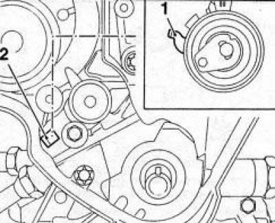
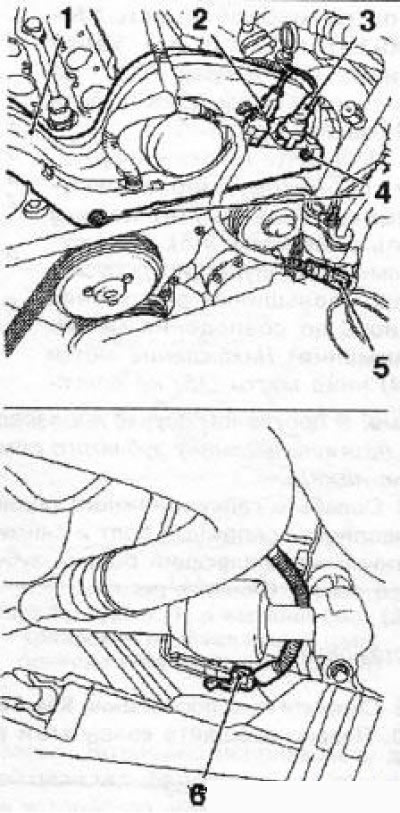
10. Having unscrewed 2 bolts and disconnect the camshaft sensor from the cylinder head (see resist. illustration)
8.10 Sensor (1) camshafts (for example the Z18XE engine): 2. Fixing bolts
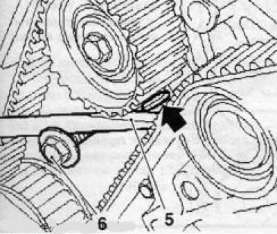
11. Check the position of the TDC for the piston of the first cylinder of the engine, check the coincidence of all marks (see illustration 8.11, I and III) and fix the position of the camshafts with a special tool (see illustration 8.11, II).
8.11 Checking the TDC position on the Z18XE engine (the arrows indicate the position of the marks with the crankshaft pulley removed): II. Special fixture KM-852
Note: If the marks on the gears do not match, it is not necessary to fix the camshafts.
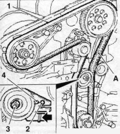
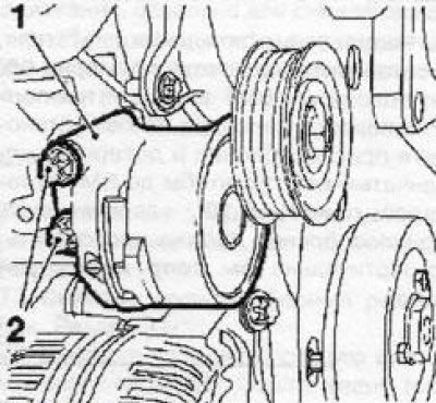
12. Loosen the mounting bolt and turn the toothed belt tensioner (see illustration) behind the adjusting eccentric in the opposite direction of the arrow (clockwise) tighten the bolt until the tension roller pointer is in front of the left stop. If necessary, mark the direction of rotation of the belt and remove it. A belt that has characteristic signs of wear, kinks and damage must be replaced without fail.
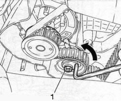
8.12 Toothed belt tensioner (engines Z16XE/Z18XE): 1. Bolt of fastening of a tension roller
13. If, when checking the adjustment of the valve timing, the marks on the timing gears did not match, after removing the belt, set the marks to the desired position by turning the camshafts and fix them with a special tool (see illustration 8.11, II).
Attention! With the belt removed, do not change the position of the crankshaft.
14. If necessary, unscrew the fixing bolt (see illustration 8.12) and remove the toothed belt tensioner. The guide roller is removed in the same way.
Installation
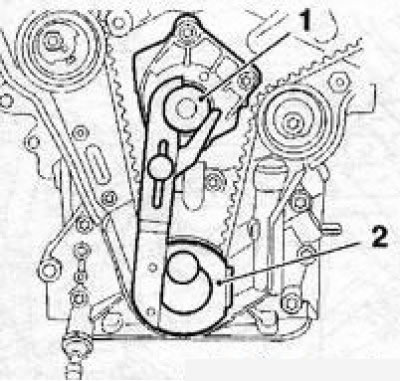
15. Install (if filmed) guide and tension rollers of the toothed belt. The idler pulley stop lever must be installed in the guide on the oil pump housing (see illustration).
8.15 Stop lever (1) guide roller must be installed in the guide (2) on the oil pump housing (engines Z16XE/ Z18XE)
Note: The tensioner fixing bolt is fully tightened to the required torque only after adjustment (see below).
16. Install the belt on the wheels and rollers so that the pulling branch (right) has been tightened, be sure to check the direction of rotation of the belt. Check alignment of all timing marks.
17. After replacing / removing the belt, it is necessary to adjust its tension, for which loosen the fastening bolt (if the video was not filmed) and turn the toothed belt tensioner (see illustration 8.12) behind the adjusting eccentric in the direction of the arrow so that the tension roller pointer is in front of the right stop, tighten the bolt.
18. Remove tool KM-852, smoothly turn the crankshaft 2 full turns clockwise and set the piston of the first cylinder to the TDC position. Reinstall the fixture to check the position KM-852, if no adjustment is required, remove it. When labels do not match (see illustration 8.11) remove and reinstall the toothed belt.
19. Slightly loosen the toothed belt tensioning roller bolt, turn the adjusting eccentric clockwise so that the position of the pointer corresponds to that shown on the resist. illustrations. Tighten the idler pulley mounting bolt to the required torque.
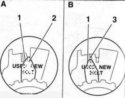
8.19 Timing belt tension adjustment: 1. Tension roller pointer; 2. Pointer position when installing a new belt (NEW); 3. Pointer position when installing a belt already used (USED)
20. Once again smoothly rotate the crankshaft 2 full turns and set the TDC position. If, after turning the crankshaft, the timing marks do not match, reinstall the belt, if the tension roller pointer deviates from the standard position, repeat the procedure for tensioning the toothed belt.
21. Installation of other removed components is made in an order of the return to an order of removal. On the Z16XE engine, lubricate the camshaft position sensor mounting bolts with a fixing compound.
Z19DT engines (H)
Removing
22. Set the engine to TDC.
23. Remove the engine top cover.
24. Remove tensioner retainer EN-46788, unscrew the fixing bolt and remove the multirib belt tensioner.
25. Remove the upper guide roller of the multirib belt.
26. Remove 5 bolts (see illustration) and remove the bracket for fixing the right engine mount, marking the position of the bolts for subsequent installation.
8.26 Lower (1) and upper (2) right engine mount bracket bolts Z19DT (H)
27. Loosen the tension roller bolt and remove the toothed belt.
Installation
28. When installing the toothed belt, place it on the gear wheels so that its pulling side is tensioned (see illustration). At the same time, observe the specified direction of rotation of the toothed belt (clockwise). Check the alignment of the TDC setting marks for the piston of the first cylinder, if necessary, set the camshafts to the required position - they must be fixed on the Z19DTH engine with special devices.
8.28 Fitting the toothed belt (1) (Z19DT engine (H)): A. The pulling side of the belt; 2. Tensioner hole; 3. A bolt of fastening of a tension roller; 4. Tension roller pointer; 5. Screwdriver; 6. Bolt
29. Tensioning the toothed belt is done with the help of an assistant, for which screw the bolt to use it as a support (see illustration), and press the adjusting lever with a screwdriver in the direction of the arrow so that the tension roller pointer is opposite the hole (see illustration 8.28). Tighten the mounting bolt.
8.29 Depressing the adjusting lever of the tension roller (Z19DTH engine)
30. Turn the crankshaft 2 full turns clockwise and set the TDC position for the piston of the first cylinder. Loosen the idler pulley mounting bolt and re-adjust the toothed belt tension. After that, tighten the roller mounting bolt with a force 30 Nm.
31. Further installation is carried out in the reverse order of removal. Tighten all threaded connections to the required torque.
Y30DT engine
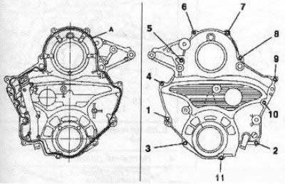
8.32 Mounting plate (4) timing gears (Y30DT engine) 1 Top Timing Cover: 2. Lower timing cover; 3. Crankcase ventilation system; 5. Cover of the upper section of the crankcase ventilation system
General information
32. A feature of this engine is the presence of a timing gear drive, through which the engine torque is transmitted to the spur gears of the high-pressure fuel pump, the water pump and to the drive gear of the camshaft drive. From the drive gear to the camshafts, the torque is transmitted through a toothed belt. The gear mechanism is mounted using a special plate (see illustration), fixed on the cylinder block, and is closed by the lower timing cover. Channels of the crankcase ventilation system are made in the upper part of the plate. The top timing cover covers the toothed belt.
Removing
33. Disconnect the battery, remove the air cleaner, raise the car on a lift and remove the crankcase protection
34. Disconnect the wiring from the engine oil temperature sensor, release it from the holders and take it aside.
35. Release the power steering hydraulic lines from the three holders.
36. Install special tool KM-6352 (see illustration), for which first install the base, and then the bracket with the bracket and screw in 2 bolts. Turn out the adjusting bolt of the tool until the bracket rests on the cylinder block, and two bolts in the upper part of the oil pan of the engine crankcase should enter the holes in the bracket (arrows).
8.36 Installation of special tool KM-6352 (1)
37. Remove the multirib belt.
38. Remove the right engine mount.
39. Turn out 4 bolts of fastening of an arm of the right support of the engine, separate a plait of electroconducting and remove an arm.
40. Turn out 2 fixing bolts and remove the right lifting eye (see illustration), then remove the 4 bolts and remove the upper timing case cover.
8.40 Right lifting eye (1) and top cover (2) timing (Y30DT engine)
41. Set the TDC of the compression stroke for the piston of the 1st cylinder.
42. Press the tension roller of the toothed belt with a spanner wrench counterclockwise and fix it with the KM-6349 tool (see illustration) and remove the toothed belt.
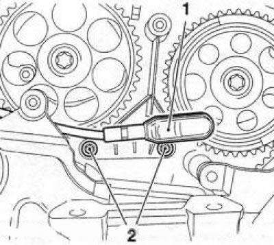
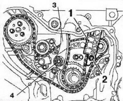
8.42 Fixing the tension roller (1) using the KM-6349 fixture (2)
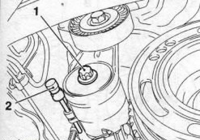
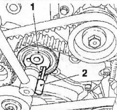
43. If it is necessary to carry out adjustment or other work with the timing gears, in order to access them, it is necessary to remove the tension and 2 guide rollers, install a tool for removing the crankshaft pulley and, holding the shaft from turning with the tool, loosen the nut securing the drive gear of the camshaft drive and remove the wheel.
44. Then it is necessary to dismantle the 2 guide rollers and the multirib belt tensioner, unscrew the fixing bolt and remove the crankshaft pulley.
45. Remove the crankcase ventilation hose (see illustration).
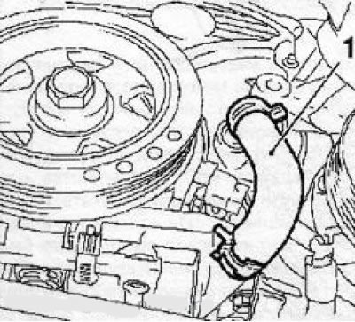
8.45 Hose (1) crankcase ventilation systems (Y30DT engine)
46. From under the car, unscrew the 5 bolts securing the lower timing cover, then lower the car, unscrew the 6 upper mounting bolts and remove the cover. Be careful not to damage mating surfaces.
47. Before removing the timing gears, screw in the bolt (M6) into a special hole on the injection pump gear and fix the gear. Then turn out 4 bolts and remove two transfer gears, and if necessary, other gears.
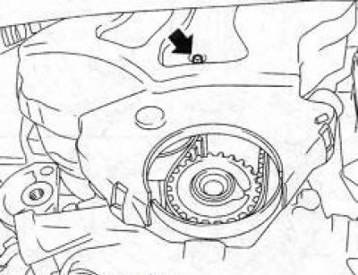
48. To set the valve timing on the gears of the high-pressure fuel pump of the crankshaft and gears, special marks are applied (see illustration), the position of the water pump drive gear does not matter. If the marks do not match, it is necessary to remove and reinstall the gears.
8.48 Timing gear installation (Y30DT engine) the arrows indicate the installation marks: 1. High pressure fuel pump gear; 2. Water pump gear; 3. Crankshaft gear; 4. Transmission gears
Note: To rotate the crankshaft, it is necessary to install the pulley in place, after the adjustment is completed, dismantle the crankshaft pulley again.
49. Use a suitable tool and remove the crankshaft oil seal and toothed belt drive wheel oil seal, being careful not to damage the seating surfaces.
Installation
50. Clean mating surfaces and lower timing cover. Apply a layer of sealant (gray color) about 2-3 thick mm on the seating edge of the cover (see resist. illustration), reinstall the bottom cover and tighten the 11 mounting bolts in the order shown (1 to 11).
8.50 Installing the lower timing cover (Y30DT engine): A. Sealant layer
Attention! Do not forget to unscrew the fixing bolt of the injection pump gear!
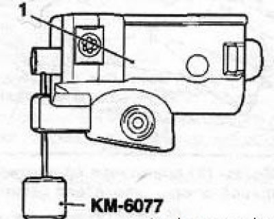
51. Press in a new crankshaft oil seal using the KM-6375 special tool and the pulley mounting bolt (see illustration 8.51a), using the KM-6376 fixture and the drive gear fastening nut (see illustration 8.51b) press in a new toothed belt drive wheel seal.
8.51a Press in a new crankshaft oil seal using tool KM-6375 (1) and fixing bolt (2) (Y30DT engine)
8.51b Press in a new toothed belt drive wheel seal using tool KM-6376 (1) and fixing nut (2) (Y30DT engine)
52. Further installation is carried out in the reverse order of removal. When installing the toothed belt, do not forget to set the TDC position of the compression stroke for the piston of the first cylinder.
Z32SE engine
Removing
53. Disconnect the wire from the negative terminal of the battery, remove the right front wheel and the multirib belt cover
54. Release the power steering hydraulic lines from the subframe holders.
55. Remove the air cleaner and right engine mount.
56. Turn out fixing bolts and remove an arm (see illustration) right engine mount.
8.56 Bracket of the right engine mount - the arrows indicate the mounting bolts (Z32SE engine)
8.56 Casing (1) cable channels (Z32SE engine): 2. Knock sensor 2-4-6 cylinders; 3. Camshaft sensor; 4. Mounting bolts; 5. Pressure sensor of the A/C system; 6. Compressor wiring connector
57. Turn out 2 fixing bolts and remove a casing (see illustration) cable channels, having previously disconnected all electrical wiring connectors.
58. Loosen the water pump pulley bolts and the 6 crankshaft pulley bolts. Remove the multirib belt, then remove the bolts and remove the water pump and crankshaft pulleys.
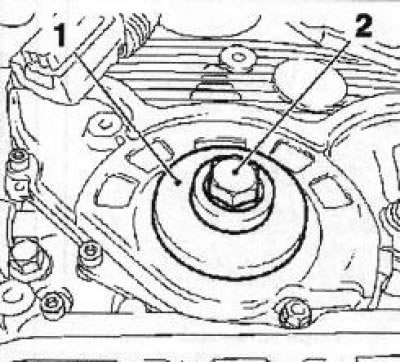
8.59 Bolts (2) tensioner attachments (1) (Z32SE engine)
59. Remove the guide roller, then remove the 2 bolts (see illustration) and remove the multirib belt tensioner.
60. Remove 5 bolts and remove the timing cover.
61. Slowly turn the crankshaft in the direction of engine rotation (clockwise) and stop without bringing about 60° to TDC of the compression stroke for the piston of the first cylinder. Install special tool KM-800-10 on the flange of the crankshaft pulley (see illustration). Turn the shaft to the TDC position of the piston of the first cylinder, - the upper part of the fixture should rest against the water pump flange, fix the fixture on the flange.
8.61 When the piston of the first cylinder is set to the TDC position of the compression stroke, the upper part of the KM-80010 tool (2) should rest against the flange (1) water pump (Z32SE engine)
62. In this position, the marks on the gears of the camshafts must match the marks on the rear timing cover (see illustration). Fix the gears of the camshafts of 2-4-6 cylinders using the KM tool800-2 (Green colour), and 1-3-5 cylinders with KM fixture800-1 (Red).
Remark: Marking «TOR» on the fixtures must point upwards.
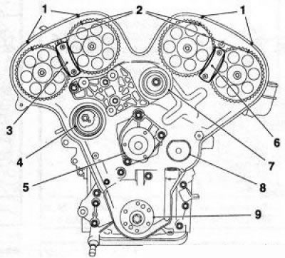
8.62 Adjusting the valve timing (Z32SE engine): 1. Marks on the rear timing cover; 2. Marks on the gears of the camshafts; 3. Adaptation KM-800-1 (Red); 4. Timing belt tensioner; 5. Water pump flange; 6. Adaptation KM-800-2 (Green colour); 7. Upper toothed belt guide roller; 8. Lower guide roller of the toothed belt; 9. Crankshaft pulley flange
63. Check the toothed belt tension (see illustration) - label (14) must be above the mark (15). With long-term operation, it is allowed to reduce the distance up to the coincidence of the marks.
Attention! Finding a Label (14) below the mark (15) not allowed! Otherwise, tension/replace the toothed belt (see below).
8.63 Toothed belt tension (16): 4. Tension roller; 14. Top mark; 15. Bottom mark; 17. Fixing nut; 18. Eccentric for pushing the roller
64. Loosen the tension roller nut, unscrew the mounting bolt and remove the lower toothed belt guide rollers. Remove the belt.
Installation
65. Remove fixture KM-80010. Slowly move the crankshaft in the direction of engine rotation, and stop without bringing about 60° to the TDC position of the compression stroke of the piston of the first cylinder. Reinstall the tool and tighten the crankshaft so that about 10°remain before TDC - the upper part of the tool must be vertical (see illustration).
8.65 When installing a toothed belt, the upper part of the KM-800-10 fixture (1) must be vertical
66. Put the timing belt on the wheels and rollers in the following sequence: camshafts 2-4-6 cylinders, upper guide roller, camshafts 3-5 cylinders, tension roller, timing belt drive wheel. When installing, pay attention to the direction of rotation of the belt and the location of the top marks (see illustration). Fasten the belt in this position using the tool KM-800-30
8.66 Fitting the toothed belt (1) (Z32SE engine): 2. Upper timing belt marks; 3. Camshaft gear 2-4-6 cylinders; 4. Top guide roller; 5. Water pump flange; 6. Adaptation KM-800-30; 7. Tension roller; 8. Camshaft gear 1-3-5 cylinders
67. Install the lower timing belt guide with a new spacer. Check the alignment of the marks on the lower branch of the toothed belt with the marks of the drive gear and the groove of the oil pump (see illustration). Tighten the guide roller bolt to the required torque.
8.67 When installing the lower tension roller (8) check the alignment of the bottom marks (12) toothed belt: 10. Fixtures KM800-10; 11. Tags on the drive gear; 13. Oil pump groove
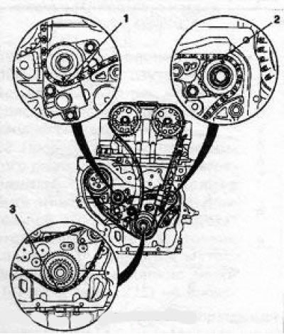
68. Remove fixture KM-80030 and turn the crankshaft to the TDC position of the piston of the first cylinder, fix the upper part of the tool KM-800-10 on the water pump flange and adjust the tension of the toothed belt by pressing the tension roller with a suitable tool on the eccentric (see illustration 8.63) counterclockwise so that the mark (14) was above the mark (15) for about 10 mm Tighten the fixing nut firmly 20 Nm. Remove fixtures KM800-10, 800-2 and 800-1 and turn the crankshaft in the direction of rotation of the engine about 660', stop the tool again KM-80010 and tighten the crankshaft to the TDC position for the piston of the first cylinder (see paragraph 61). Check again check the position of the tension roller marks - the distance between the marks should be 3-4 mm (on a previously used belt, marks can be combined). Repeat the adjustment if necessary. 39 Check the alignment of the marks of the gear wheels of the camshafts (see illustration 8.62). Further installation is carried out in the reverse order of removal.
Z22YH/Z22SE/Z20NET engines
Note: The procedure for removing/installing drive chains for 2.2L engines is described below. On the Z20NET engine, instead of the ignition module, 4 ignition coils are installed, separately for each candle, - features (not listed below) dismantling/installation are associated only with these elements.
Removing
71. Set the piston of the 4th cylinder to the TDC position of the compression stroke.
72. Remove the multirib belt.
73. Remove the front section of the exhaust system.
74. Turn out axial bolts of forward and back support of the engine.
75. Remove the camshaft sensor.
76. Turn out 2 fixing bolts (see illustration) and remove the upper timing chain guide.
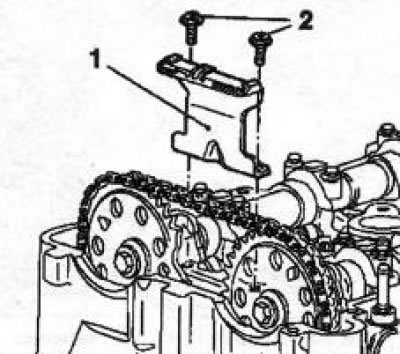
8.76 Bolts (2) top rail fixings (1) timing chains (on the example of the Z22YH engine)
77. Remove the timing chain tensioner (see illustration).
8.77 Tensioner (1) timing drive goals (on the example of the Z22YH engine)
78. Remove the mounting bolt and remove the exhaust camshaft sprocket, - hold the shaft from turning by the hexagonal part with a wrench.
79. Install a special transverse beam above the engine compartment for hanging the power unit, which is mounted on the side members, and install a set of rigging equipment. It is possible to use a hoist or other winch-type lifting device for this purpose.
80. Loosen the bolts and nut securing the right engine mount and lift the power unit with the installed equipment and remove the bolts.
81. Turn out 3 fixing bolts (see illustration) and remove the bracket for attaching the right support to the engine block.
8.81 Bolts (2) bracket mounting (1) right engine mount (Z22YH engine)
82. Turn out a bolt of fastening of the tension device of a multirib belt and remove it.
83. Turn out the plug and the upper bolt of the timing chain guide (see illustration).
8.83 Plug (1) and top bolt (2) Timing chain guide fasteners (Z22YH engine)
84. Turn out 4 top bolts (see illustration) fastening the timing cover, lower the engine slightly and remove the bolts.
8.84 Timing cover (on the example of the Z22YH engine) - the arrows indicate the upper mounting bolts: 1. Crankshaft pulley
85. Drain the oil from the crankcase, unscrew the mounting bolt and remove the crankshaft pulley.
86. Turn out 7 bolts and remove the timing cover.
Note: Bolts are installed with washers.
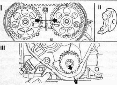
87. Remove the lower mounting bolt (see illustration) timing chain guide and remove it. Then remove the lower timing chain tensioner guide bolt, lower the vehicle and remove the tensioner guide through the top. Remove the timing chain. Jack up the vehicle again and remove the timing drive sprocket.
8.87 Timing chain guides (on the example of the Z22YH engine): 1. Chain guide; 2, 4. Lower fixing bolts; 3. Chain tensioner guide
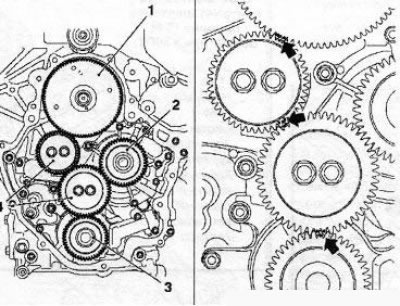
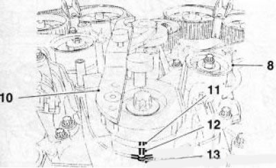
88. Remove 2 bolts (see illustration) and remove the balance shaft drive chain tensioner. Then alternately unscrew the mounting bolts and remove the tensioner guide, upper and lower guides. Remove the compensation shaft drive chain.
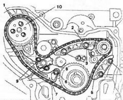
8.88 Chain (1) compensation shaft drives (Z22YH engine): 2. Top guide; 3,4,6,9. Mounting bolts; 5. Bottom guide; 7. Chain tensioner guide; 8. Tensioner; 10. Water pump sprocket
Installation
89. Install the compensation shaft drive chain on the sprockets, observing the following sequence (see illustration): compensation shaft intake side, crankshaft (then fix the chain with a plastic wedge), water pump compensation shaft on the side of the exhaust valves. When installing the chain, its colored links must match the corresponding marks on the sprockets.
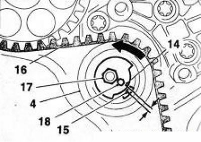
8.89 Installing the compensation shaft drive chain: 1. Label of the final compensation shaft; 2. Label of the inlet compensation shaft; 3. Pinion mark
90. Further installation is carried out in the reverse order of removal. Do not forget to replace the crankshaft oil seal, press in a new oil seal using the appropriate tool.
91. Before installing the chain tensionercompensation shaft drive, it must be fixed in the depressed position using a special tool or other suitable tool (see illustration 8.91a). Remove the retainer after installation. Before installing the timing chain tensioner, you must first replace its seals and reassemble it with a vise (see illustration 8.91b), while the internal tensioner piston should lock in the depressed position. After installing the tensioner, it is necessary to remove the fixation of the inner piston, for which press with a suitable tool on the timing chain in the area of the tensioner guide (see illustration 8.91c).
8.91а Tensioner (1) compensation shaft drive chains
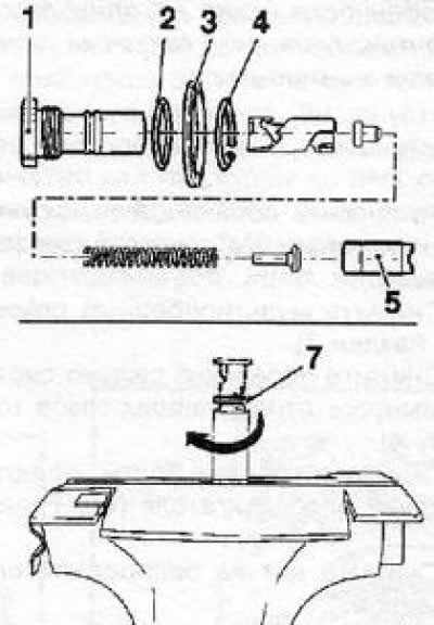
8.91b Tensioner Assembly (1) timing chains:
2, 3. Gaskets; 4. Retaining ring; 5. Internal piston; 7. Retainer of the inner piston in the depressed position
8.91с Removing the fixation of the internal piston of the timing drive tensioner (Z22YH engine)
Y20DTH/Y22DTR engines
92. The operation to replace the timing drive elements is quite complicated and therefore is not given here. To remove the single-row timing chain, you need to remove the engine head, and to remove the double-row chain, you need to remove the engine.
Visitor comments