
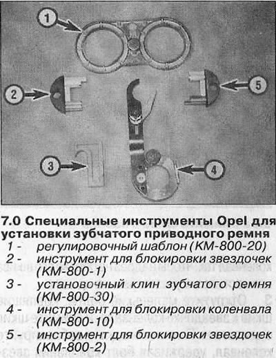
Attention! Fine adjustment of the timing belt tension requires the use of the following Opel special tools: Locking tools for camshaft sprockets (KM-800-1 and KM-800-2) and crankshaft sprockets (KM-800-10), belt wedge (KM-800-30) and adjusting template for camshaft sprockets (KM-800-20) (see illustration). If the belt is installed without the use of special tools, have an Opel dealer check the belt tension as soon as possible.
Attention! Removal and installation of a gear belt can be made only on the cold engine.
Removing
1. Disconnect the negative cable from the battery and bring piston No. 1 to TDC on the compression stroke (see chapter 3).
Attention! On models with anti-theft system Opel (ATWS), the negative wire must be separated from the battery terminal within 15 seconds after the ignition is turned off, otherwise the alarm will sound.
2. Remove the crankshaft pulley as described in chapter 5.
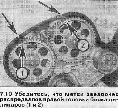
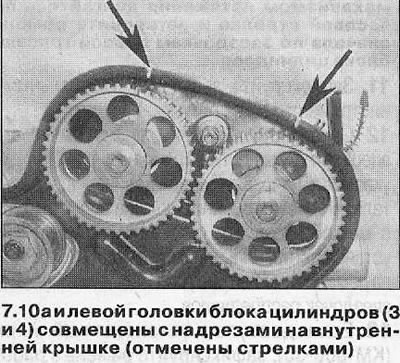
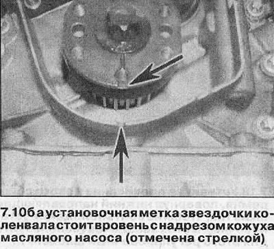
3. Make sure that the camshaft sprocket alignment marks are aligned with the marks on the timing belt cover, and the crankshaft sprocket mark is flush with the notch on the oil pump housing.
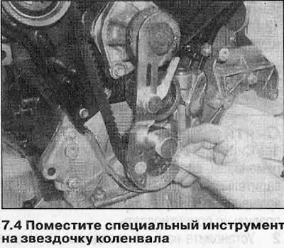
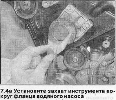
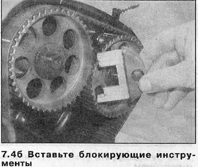
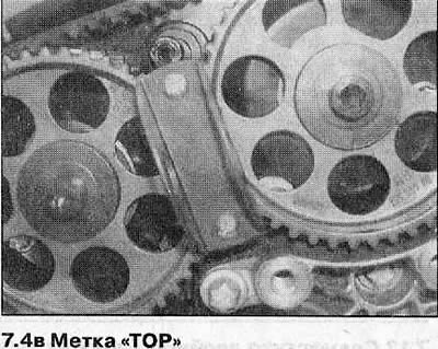
4. Place the special tool KM-800-10 on the crankshaft sprocket and block the shaft in this position by setting the tool grip around the water pump flange. Block the camshafts with the appropriate tools, setting the latter with a mark «TOR» up. The sprockets of the right cylinder head must be blocked with the KM-800-1 tool (it has the numbers 1 and 2, the handle of the tool is painted red), sprockets of the left head - with the KM-800-2 tool (marked with numbers 3 and 4, the handle is painted green) (see illustrations).
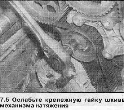
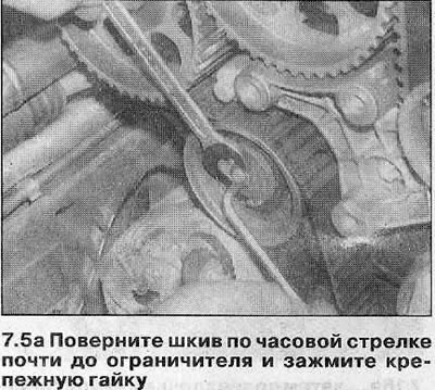
5. Loosen the toothed belt tensioner pulley nut. Using a hex wrench, turn the tensioner pulley clockwise almost to the stop and tighten the pulley nut (see illustrations).
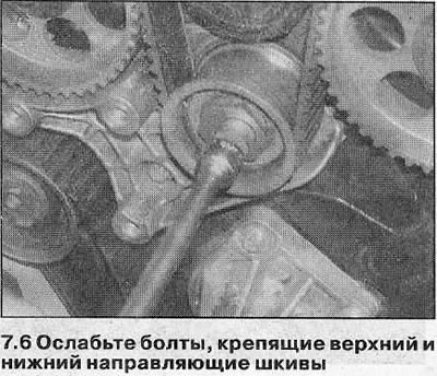
6. Loosen the bolts securing the upper and lower toothed belt guide pulleys (see illustrations).
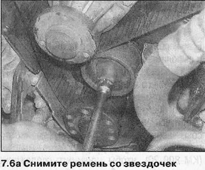
7. Pull the toothed belt off the sprockets and remove it from the engine. If the belt will not be installed immediately and you do not have the special tools, turn the crankshaft against its stroke by about 60°to move the pistons away from the valves.
8. Check the toothed belt for signs of uneven wear, cracks, oil contamination and replace it if there is even the slightest doubt about the condition of the component. If the corresponding marks are no longer visible on the outside of the belt, the belt must be replaced regardless of its condition (see point 12). If the engine needs to be overhauled, the vehicle has traveled more than 65,000 km, or the belt has been in operation for more than 4 years, replace the belt, regardless of its condition (since 1997, the belt change interval has been extended to 130,000 km or 8 years). If the belt is contaminated with oil, find the cause of the leak and fix it. Rinse the belt and all associated components to remove any oil.
Installation
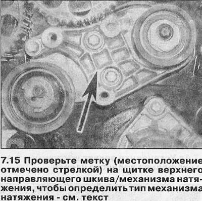
Attention! The engines described are fitted with two different types of toothed belts/tensioners and are not interchangeable. Modified tensioner/timing belt assembly used as standard on late models (since 1997), requires less frequent belt replacement (every 130,000 km or 8 years). You can tell the modified assembly from the regular assembly by the letter stamped on the top guide roller/tensioner pulley support plate. The conventional tensioner is marked with a D, while the modified mechanism has an E (EA or EB) (see illustration 7.15).
9. When reassembling, thoroughly clean the timing belt sprockets and tensioner pulleys.
10. Make sure that the crankshaft sprocket alignment mark is still aligned with the notch on the oil pump housing, and the camshaft sprocket marks are aligned with the marks on the inner belt cover (see chapter 3) (see illustrations). If the crankshaft has been moved 60°, return it to TDC.
11. Block the sprockets with special tools as described in point 4.
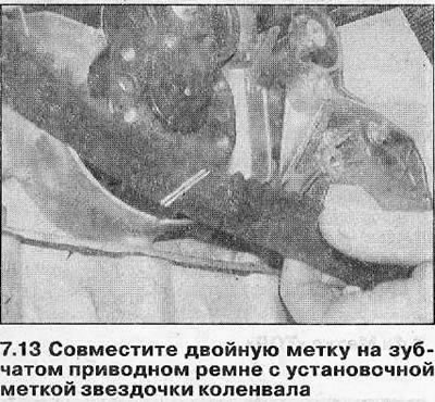
12. Orient the belt according to the marks on its outer surface. The arrows on the belt should indicate the direction of rotation of the engine shafts, and the double line should align with the crankshaft sprocket mark. If the belt is installed correctly, the four separate lines on the belt will line up with the timing marks on the camshaft sprocket.
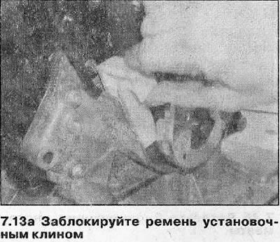
13. If a mounting wedge is available (KM-800-30), lock the belt in working position by inserting the tool between the right belt run and the inner cover (see illustrations).
14. Check the identification mark on the top idler/tensioner pulley support plate (see note above).
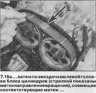
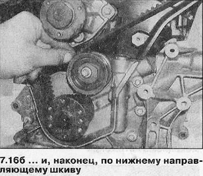
15. On early model engines with a conventional tensioner (label «D» - see illustration), install the toothed belt on the lower guide pulley, then around the left cylinder head camshaft sprockets, matching the marks. Install the belt over the upper guide pulley, then over the right cylinder head camshafts, aligning the marks again.
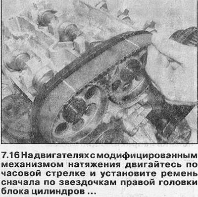
16. On engines with a modified tensioner (the label contains the letter E - see illustration 7.15) put the belt behind the tensioner pulley, then install it on the camshaft sprockets of the right cylinder head, aligning the corresponding marks. Install the belt on the upper guide pulley, then on the camshaft sprockets of the left cylinder head, also aligning the marks (see illustrations).
17. On all engines, check that the belt teeth are correctly seated in the sprockets and that the sprockets/belt alignment marks are aligned.
If necessary, remove the belt from the sprockets and make the necessary adjustments.
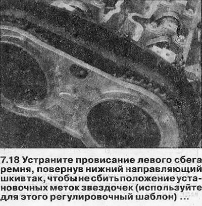
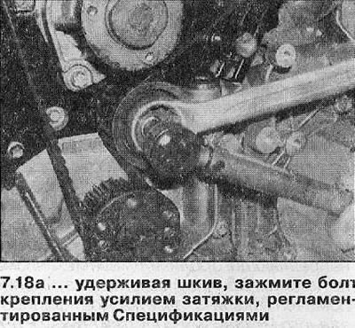
18. Loosen the lower idler pulley bolt. Turn the pulley counter-clockwise to remove slack on the left side of the belt (but don't drag it). Make sure the alignment marks are still aligned, remove the locking tools and use the adjustment template (KM-800-20), to check the position of the sprocket marks. Tighten the pulley mounting bolt with a torque specified specifications (see illustrations).
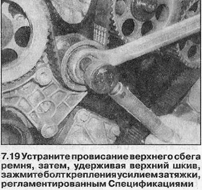
19. Loosen the upper idler pulley bolt. Turn the pulley counterclockwise to remove slack from the top run of the belt (but don't drag it). Make sure the sprocket alignment marks are still aligned. Tighten the pulley mounting bolt with a torque specified specifications (see illustration).
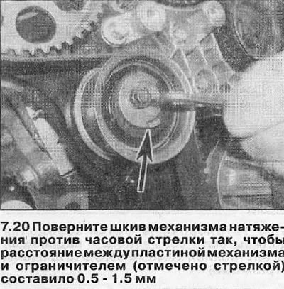
20. Loosen the toothed belt tensioner pulley nut, then use the Allen key to turn the tensioner arm counterclockwise so that the distance between the mechanism plate and the limiter is 0.5-1.5mm (see illustration). While holding the tensioner pulley in this position, securely tighten the mounting nut.
21. Remove all special tools, then install a socket on the crankshaft sprocket bolt and rotate the crankshaft two full turns (720°) in the direction of its rotation to adjust the position of the components.
22. Make sure that the alignment marks of all sprockets are aligned with the corresponding marks, then loosen the tensioner nut again.
Attention! Please note that the belt alignment marks should no longer match the sprocket marks; they serve only for the initial orientation of the belt.
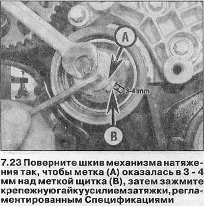
23. Using a hex wrench, turn the tensioner pulley so that the mark on the tensioner plate is 3 - 4 mm higher than the mark on the guard stop (see illustration). While holding the tensioner in this position, tighten the fixing nut with a tightening torque specified specifications.
24. Turn the crankshaft two more full turns along its course.
25. Block the crankshaft in this position with the special tool KM-800-10 and check the alignment of the alignment marks of the camshaft sprockets using the adjusting template (KM-800-20).
26. If special tools are not available, make sure that the crankshaft sprocket alignment mark is flush with the notch on the oil pump casing, and the sprocket marks of all camshafts are aligned with the notches on the inner belt cover.
27. If adjustment is necessary, repeat steps 18-26.
28. Once the alignment marks are aligned, install the timing belt cover and crankshaft pulley as described in Chapters 5 and 6.
Attention! If the installation was carried out without the use of special tools, have an Opel dealer check the belt tension at the first opportunity.
Visitor comments