
Removing
1. Remove the toothed drive belt as described in Chapter 7.
2. Remove all camshaft sprockets, crankshaft sprocket, upper idler pulley/belt tensioner pulley assembly and lower idler pulley (see chapter 8).
3. Turn off bolts of fastening and remove from the engine an internal cover of a gear belt (see chapter 6).
4. Remove the small sump section, downpipe/oil pump strainer and main sump section (see chapter 12).
5. Remove the lower alternator mounting bolt, then loosen the upper bolt and rotate the alternator on it to move it away from the oil pump housing.
6. Disconnect the wiring connector from the oil pressure switch, then remove the bolt securing the wire harness guide to the front of the pump housing.
7. Remove the mounting bolts, then pull the oil pump housing assembly off the end of the crankshaft, being careful not to lose the dowel pins. Remove the casing gasket - it must be replaced.
Bulkhead
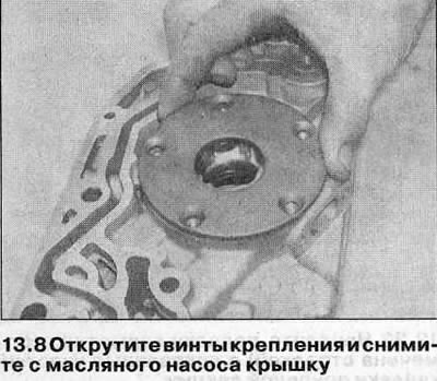
8. Loosen the fixing screws and remove the pump cover (see illustration).
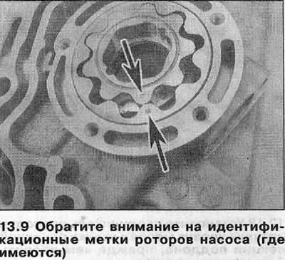
9. Mark the top side of the pump rotors with a marker to orient them correctly when reinstalling. On some models, the rotors are factory marked (see illustration).
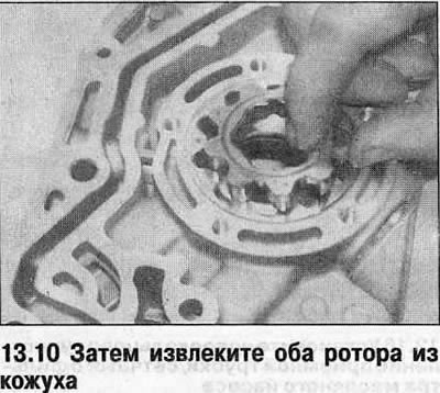
10. Remove the rotors from the pump casing (see illustration).
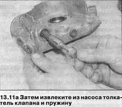
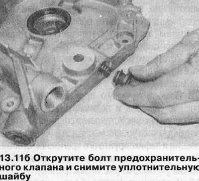
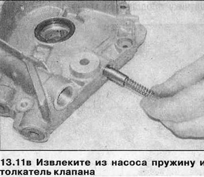
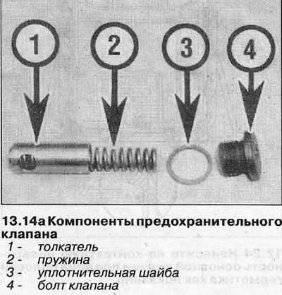
11. Turn out from the top part of a casing bolts of the reducing oil valve and the safety valve and take springs and pushers of valves, having remembered their orientation in the pump. Remove the sealing washers from the valve bolts (see illustrations).
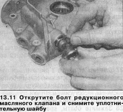
Attention! The bypass valve can be removed without removing the pump from the engine by simply removing the outer timing belt cover.
12. Clean the components and carefully inspect the rotors, pump housing and valve lifters for nicks and signs of wear. Replace components as needed; if the rotors or pump casing are scratched, the complete pump assembly must be replaced.
13. If the components appear serviceable, measure the axial clearance of the rotors and check the pump cover for deformation. If the clearances are outside the specification tolerances, replace the pump.
14. If the condition of the pump is satisfactory, assemble the components in the reverse order of removal, paying attention to the following:
- A) Make sure both rotors are oriented according to the marks made before removal.
- b) Tighten the pump cover screws with a tightening torque specified specifications.
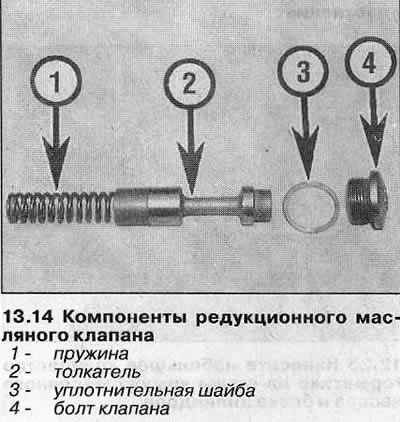
- V) Install new o-rings on the valve bolts and make sure their tappets and springs are correctly oriented (see illustrations).
- d) Finally, prime the oil pump with clean engine oil by rotating the inner rotor.
Installation
15. Before installation, it is necessary to determine which of the three types of oil pump is installed on this engine. Determine the diameter of the oil pump mounting bolts. In 1999, the diameter was increased from M6 to M8. If M6 bolts are used, inspect the oil pump cover/inner timing belt cover (see illustration). The modified cover has an additional hole giving access to the top oil pump bolt (No. 6 in tightening sequence).
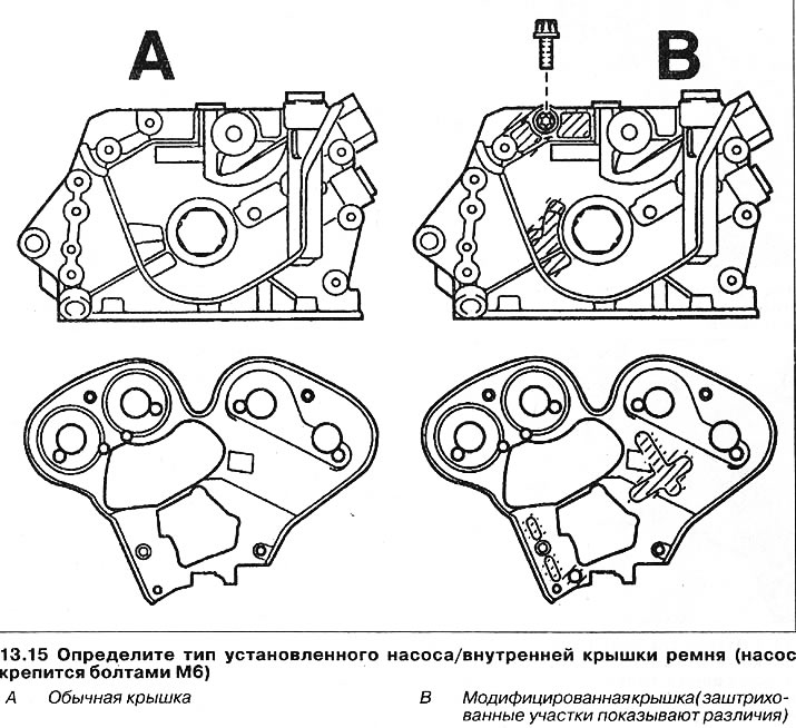
Oil pump with M6 mounting bolts and conventional inner toothed belt cover
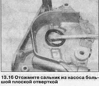
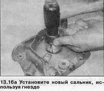
16. Before installing, carefully pry out the crankshaft oil seal using a flathead screwdriver. Lubricate the sealing lip of the new oil seal with clean engine oil and install with the lip facing in. To do this, use a tubular drift that rests only on the hard outer edge of the seal (see illustrations). The seal should line up with the casing.
17. Be convinced that contact surfaces of the oil pump and the block of cylinders pure and dry, and adjusting pins — in a working position.
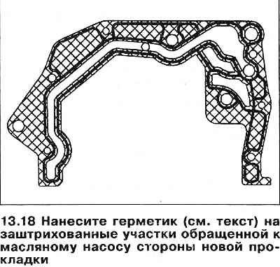
18. Apply a thin layer of sealant (Opel recommends compound 15 03 170) approximately 0.2 mm thick on the shaded areas on the oil pump side of the new gasket (see illustration).
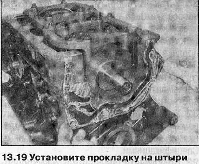
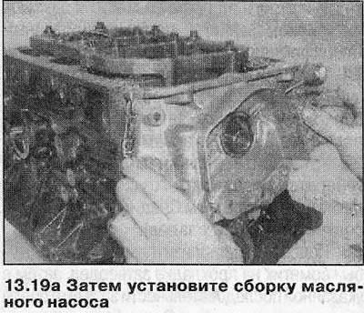
19. Install the gasket on the cylinder block, then carefully move the oil pump into position and fit the inner rotor onto the end of the crankshaft. Install the pump on the pins, being careful not to damage the sealing lip of the stuffing box (see illustrations).
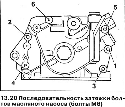
20. Install the pump casing fastening bolts, each strictly in the same place and tighten them with the tightening force regulated specifications (see illustration).
21. Install the lower toothed belt guide pulley on the pump and tighten the fastening bolt with a tightening torque regulated specifications.
22. Install the lower mounting bolt of the generator and tighten it with a tightening torque regulated specifications (see related section).
23. Wait approximately 10 minutes for the sealant on the gasket to harden, then tighten the bolts in sequence with torque (see specs).
24. Remove the lower idler pulley from the oil pump, install the inner toothed belt cover (see chapter 6) and tighten the fastening bolts with a tightening force regulated specifications.
25. Connect the oil pressure sensor wiring connector and attach the wire harness guide to the operating position with the bolt.
26. Install the main sump, downpipe/oil pump strainer, and small sump as described in Chapter 12.
27. Install sprockets, idler pulleys and toothed belt tensioner, then install belt (see chapters 7 and 8).
28. Finally, install a new oil filter and fill the engine with clean oil (see related section).
Oil pump with M6 mounting bolts and modified inner toothed belt cover
29. Follow the steps described in paragraphs 16-19.
30. Install the pump casing mounting bolts (each strictly in the same place) and tighten them to the torque specified in the Specifications in the order shown (see illustration 13.20).
31. Install the lower mounting bolt of the generator and tighten it with a tightening torque regulated specifications (see related section).
32. Install the inner toothed belt cover (see chapter 6) and tighten the fastening bolts with a tightening force regulated specifications.
33. Connect the oil pressure sensor wiring connector and attach the wire harness guide to the operating position with the bolt.
34. Install the main sump section, downpipe/oil pump strainer and small sump section (see chapter 12).
35. Install sprockets, idlers and toothed belt tensioner, then install belt (see chapters 7 and 8). Before installing the outer toothed belt cover, re-tighten all the oil pump mounting bolts to the torque specified in the Specifications in the sequence shown (see illustration 13.20).
36. Finally, install a new oil filter and fill the engine with clean oil (see related section).
Oil pump with M8 mounting bolts
37. Remove all traces of blocking compound from the threads of the oil pump mounting bolts.
38. Follow the steps described in paragraphs 16-19.
39. Apply some blocking compound (Opel recommends using 15 10 181) on the threads of each pump mounting bolt, then install the bolts, each strictly in its original place, and tighten them by hand.
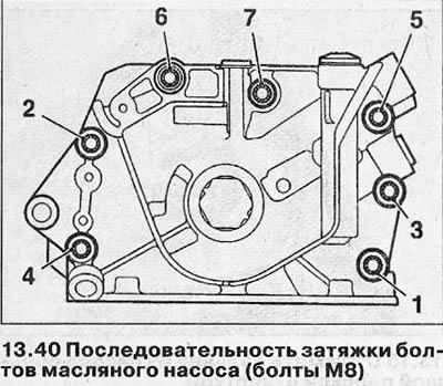
40. In the indicated sequence, tighten all the pump mounting bolts with the tightening torque specified specifications (see illustration).
41. Install the lower mounting bolt of the generator and tighten it with a tightening torque regulated specifications (see related section).
42. In the same sequence, tighten the pump mounting bolts with the required tightening torque (see specs).
43. Connect the oil pressure sensor wiring connector and attach the wire harness guide to the operating position with the bolt.
44. Install the inner toothed belt cover (see chapter 6) and tighten the fastening bolts with a tightening force regulated specifications.
45. Install the main sump, downpipe/oil pump strainer, and small sump as described in Chapter 12.
46. Install sprockets, idler pulleys and toothed belt tensioner, then install belt (see chapters 7 and 8).
47. Finally, install a new oil filter and fill the engine with clean oil (see related section).
Visitor comments