


Contents: Removal ⬇ Installation ⬇
Removal
Small section of the pallet
Please note: New small pan section mounting bolts will be required for installation.
1. Disconnect the negative cable from the battery.
Caution! On models with Opel Anti-Theft System (ATWS), the negative cable must be disconnected from the battery terminal within 15 seconds after the ignition is turned off, otherwise the alarm will be triggered.
2. Apply the handbrake, then jack up the front of the car and place it on axle stands. Unscrew the mounting screws and remove the lower shield from under the engine.
3. Drain the engine oil (see the relevant section), then install a new sealing washer and tighten the drain plug to the specified tightening torque Specifications.
4. Disconnect the wiring harness connector from the oil level sensor on the right side of the main pan section, then pull out the retaining clip and push the connector into the pan (see illustration).
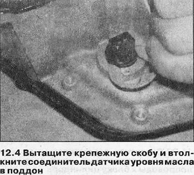
5. Loosen the bolts securing the small section of the pan, then separate it from the main section and remove it together with the gasket. Do not damage the oil level sensor wiring.
6. If necessary, unscrew the mounting bolts (access to one of them is extremely difficult) and remove the suction tube/strainer from the base of the oil pump housing together with the O-ring. Check the oil strainer for blockages and damage and replace/clean it if necessary.
Main section of the pallet
Please note: Installation will require new subframe mounting bolts and new center tie rod retaining nuts.
7. Remove the small pan section and the pickup tube/strainer as described in steps 1-6.
8. On models with Xenon headlights, disconnect the wiring connector from the front longitudinal vehicle roll sensor (see the relevant section), then detach the rod from the ball joint of the sensor lever.
9. Remove the central steering rod (see the relevant section).
10. Loosen the mounting bolts and remove the vibration dampers from the left and right engine mounts.
11. Loosen and remove the nuts securing the left and right hangers to the subframe.
12. Attach a winch to the engine mounting eyes, then lift the engine to take the load off the hangers. Alternatively, use a special stand installed across the engine bay.
13. Unscrew the front subframe mounting bolts (see the relevant section) approximately 4 turns. Support the rear of the frame with a jack, then loosen and remove the rear suspension bolts. Lower the rear of the subframe approximately 10 cm to gain access to the main pan section.
14. Loosen the bolts securing the main section flange to the transmission case, then gradually loosen and remove the bolts securing the main section to the cylinder block/oil pump base. Separate the section from the engine by hitting it with the palm of your hand, then remove it from under the vehicle. Remove the seal - it must be replaced.
Caution: If the pan sections are not installed immediately, raise the engine subframe into position and install the mounting bolts, then lower the rear of the engine onto the subframe.
Installation
Small section of the pallet
15. Clean all dirt and oil from the mating surfaces of the oil pan sections and the oil strainer/oil pump housing.
16. Where necessary, place a new O-ring on the top of the intake pipe, then install the mesh oil receiver and tighten its mounting bolts to the specified tightening torque Specifications (see illustration).
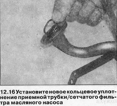
17. Install a new O-ring onto the oil level sensor wiring connector.
18. Place the new gasket on the small pan section and lift the small pan section up to the main section. Install the oil level sensor wiring connector into the wall of the main section and secure it with the retaining clip, then install the small pan section onto the main section (see illustration).
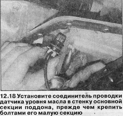
19. Install the new small pan section mounting bolts, then tighten them in a diagonal sequence to the required tightening torque (see Specifications). Tighten the bolts to the required angle (see Specifications). It is recommended to use a corner template for this to ensure accuracy.
20. Connect the oil level sensor wiring connector, then install the engine lower shield.
21. Lower the vehicle to the ground, then fill the engine with fresh oil (see the relevant section).
Main section of the pallet
22. Clean all dirt and oil from the mating surfaces of the main section and cylinder block.
23. Make sure the main section seal groove is dry, then apply a bead of sealant into it (Opel recommends using composition 15 03 298) (see illustration).
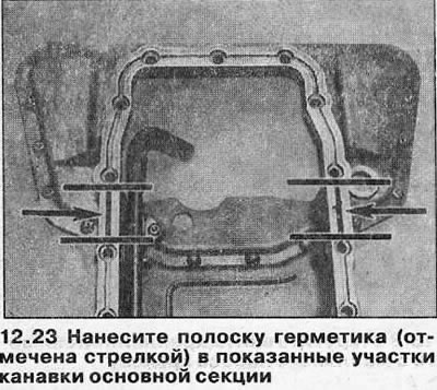
Caution: If Opel sealant is used, the main section must be bolted within ten minutes of application.
24. Install the new seal into the groove, then apply a bead of sealant approximately 3 mm wide to the surface of the main section (see illustrations). The sealant should go in the front part of the main section along the outer side of the seal, and in the rear part - along the inner edge of the seal. There should be two stripes of sealant on the middle sections of the contact surface of the section.
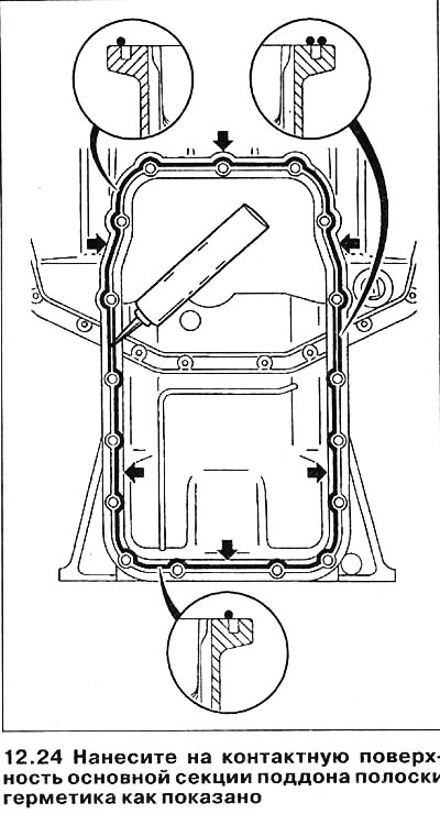
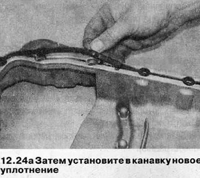
25. Apply a small amount of suitable sealant (Opel recommends using composition 15 03 295) on the areas of the contact surface of the cylinder block around the joints of the oil pump casing and the rear main bearing cover (see illustrations).
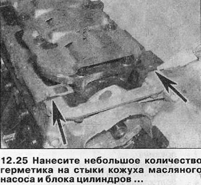
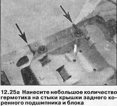
26. Move the main section of the tray into the working position and tighten the bolts that secure it.
27. Working from the center in a diagonal sequence, gradually tighten the main section mounting bolts to the cylinder block/oil pump to the specified tightening torque Specifications.
28. Tighten the bolts securing the main section flange to the transmission housing with the specified tightening torque Specifications.
29. Raise the subframe to its operating position so that the engine mount tabs fit into the corresponding slots in the frame. Install the four new rear mounting bolts, then remove the front subframe mounting bolts and install new ones. Tighten the frame mounting bolts to the specified torque Specifications, then turn them to the desired angles (see the relevant section).
30. Unhook the winch/special stand from the engine, then install the nuts securing the engine hangers to the subframe and tighten them to the specified tightening torque Specifications. Install vibration dampers on the hangers and tighten their mounting bolts with the specified tightening force.
31. Install the central steering rod (see the relevant section).
32. On models with Xenon headlights, attach the tie rod ball joint to the front vehicle roll sensor and connect the wiring harness connector (see the relevant section).
33. Install the small section of the tray as described in points 15-21.
Visitor comments