
2. Remove the camshaft sprockets (see chapter 8). If it is necessary to remove the right cylinder head camshafts, turn both camshafts counterclockwise by approximately 60°to relieve valve spring pressure on the camshaft bearing caps. The camshafts of the left cylinder head are best left at TDC.
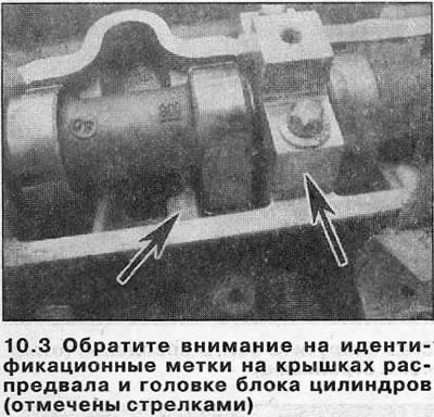
3. Start with the intake camshaft. Working in a spiral from the outside to the inside, loosen the shaft bearing cap bolts a half turn in one go to gradually relieve the valve spring pressure on the bearing caps. Unscrew the bolts completely and remove them together with the covers. Bearing caps are numbered so that later they can be installed each in its original place (see illustration).
Attention! If the bearing cap bolts were carelessly loosened, the caps could break. If damage is found on at least one of the covers, replace the complete cylinder head assembly - covers are not sold separately.
4. Take a cam-shaft from a head of the block of cylinders and pull out an epiploon. Mark the intake camshafts with paint or a marker to avoid mixing up the shafts during installation, which could increase the wear rate.
5. Repeat steps 3 and 4 on the exhaust camshaft. If work is being done on the left cylinder head, remove the camshaft sensor bolts before removing the bearing caps (see related section), move it away from the front bearing cap and free the knock sensor wiring harness.
6. Prepare twelve small clean plastic containers (by number of valves) and number them; alternatively, divide a large container into compartments. Remove the valve lifters one by one, placing them in a container with the corresponding number (see illustrations). Do not mix up components from different cylinders, this will accelerate their wear.
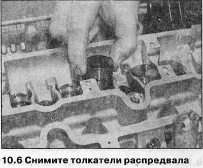
Attention! Store hydraulic tappets without turning them upside down, otherwise oil will leak out of them.
7. If necessary, repeat the steps described in paragraphs 1-6, and remove the camshafts and pushers from the other cylinder head. If all camshafts must be removed at the same time, mark them as well as the bearing caps so as not to mix up components during installation.
Inspection
8. Inspect the running surfaces of the bearings and camshaft lobes for scratches and gouges. Replace the camshaft if such damage is found. If the cylinder head running surfaces are excessively worn, replace the head.
9. Examine contact surfaces of pushers with cams on presence of the developed places and scratches. Check the walls of the tappets, as well as the holes under them in the cylinder head for damage and signs of wear. If the pusher is suspected to be defective or appears to be worn, it should be replaced.
Installation
10. Where removed, lubricate the tappets with clean engine oil and carefully insert each into its original place in the cylinder head.
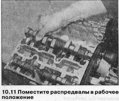
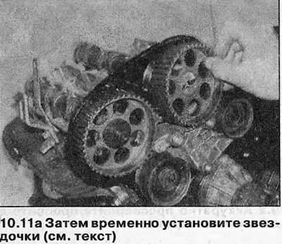
11. Place camshafts in working position. Make sure the crankshaft is still at approximately 60°BTDC, then temporarily install the camshaft sprockets (see chapter 8) (see illustrations). On the left cylinder head, position the camshafts so that the alignment marks of the sprocket are aligned with the notches on the inner belt cover, and on the right cylinder head, position the shafts so that the alignment marks of the sprockets are approximately 60°from the notches on the cover (up to TDC). This will distribute the pressure of the valve springs evenly across each of the camshafts.
12. Make sure that the contact surfaces of the bearing caps and cylinder head are clean and dry and lubricate the cams and camshaft bearing journals with clean engine oil.
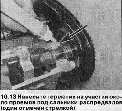
13. Apply a small amount of sealant (Opel recommends compound 15 03170) on the contact surfaces of the cylinder head near the openings for the camshaft seals (see illustration).
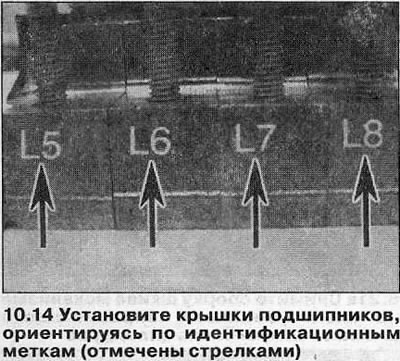
14. Install the camshaft bearing caps and mounting bolts, each component strictly in its original place. The exhaust camshaft covers are numbered 1 to 4 and the intake camshaft covers are numbered 5 to 8. The same numbers are stamped on the cylinder head (see illustration).
15. Install the bearing cap bolts on the exhaust camshaft.
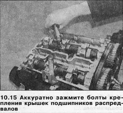
Moving in a spiral from the center to the periphery, gradually tighten the bolts (half a turn in one step) so that all covers sit on the cylinder head. Then tighten the bolts with a torque specified specifications (see illustration).
Attention! If the bearing cap bolts are not tightened carelessly, the caps may break. In this case, you will have to replace the complete cylinder head assembly - bearing caps are not sold separately.
16. Tighten the intake camshaft bearing cap bolts as described in paragraph 15.
17. If removed, install the camshafts of the opposite cylinder head in the same way.
18. Install new camshaft seals as described in Chapter 9.
19. Install the camshaft sprockets (see chapter 8).
20. Make sure the camshaft sprocket alignment marks line up with the slots on the inner belt cover, then carefully rotate the crankshaft along its stroke to align the sprocket mark with the notch on the oil pump housing.
21. Install the toothed belt as described in Chapter 7.
22. Install valve covers and toothed belt cover (see chapters 4 and 6).
Visitor comments