
Camshaft sprockets
Attention! Installation will require new sprocket mounting bolts.
Removing
1. Remove the toothed belt as described in Chapter 7. Rotate the crankshaft about 60°against its stroke to move the pistons away from the valves.
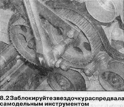
2. Block the camshaft in one of two ways:
- A) Make a blocking tool from two pieces of steel strip (one is long, the other is short), and three bolts with nuts. One of the bolts forms the hinge of the forked tool, the two remaining bolts connect its ends to the sprocket (see illustration),
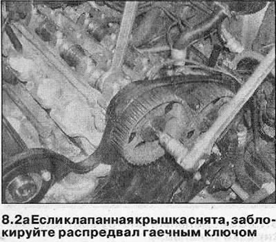
- b) Remove the valve cover (see chapter 4) and block the camshaft with a wrench (see illustration).
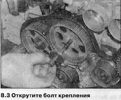
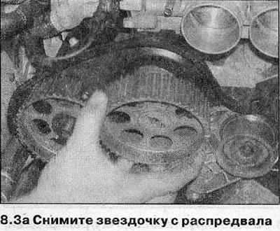
3. Remove the mounting bolt and remove the sprocket from the end of the camshaft (see illustrations). If the sprocket dowel pin is loose at the end of the camshaft, remove it and store it with the sprocket so you don't lose it.
4. If necessary, remove remaining sprockets using the same method.
Installation
5. Before installing the sprocket, check the camshaft oil seal for damage and leaks. If necessary, replace it as described in Chapter 9.
6. Place the dowel pin in working position.
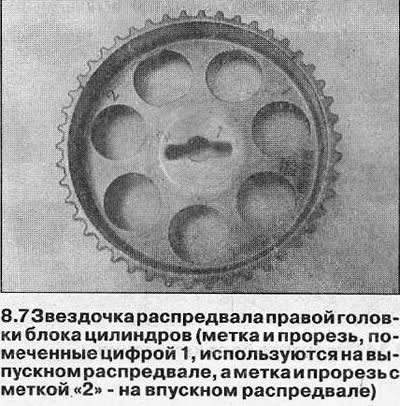
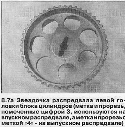
7. Please note that the sprockets of the right cylinder head are marked 1 and 2, the sprockets of the left head are marked 3 and 4. The camshaft sprockets of each of the heads are the same, each is equipped with two slots for the locating pin and two marks. When installing the sprocket, it is important to use the correct slot and mark (see illustrations and table).
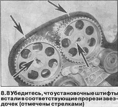
8. Make sure the camshaft locating pin is in the correct slot in the sprocket, then install the washer and new mounting bolt (see illustrations).
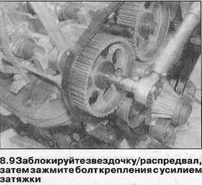
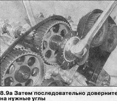
9. Block the sprocket using the method used to remove it and tighten the mounting bolt to the torque (see specs), then sequentially tighten the bolt to the desired angle (see specs), using socket and extension rod (see illustrations). It is recommended to use an angle template for this to ensure accuracy. If a template is not available, apply alignment marks to the bolt head and flywheel to help ensure the bolt is rotated to the correct angle.
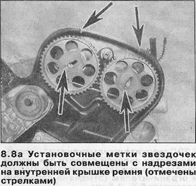
10. Make sure that the proper camshaft sprocket alignment marks are aligned with the notches on the inner belt cover, then carefully turn the crankshaft in the direction of rotation so that its sprocket mark is flush with the notch on the oil pump housing.
11. Install the toothed belt as described in Chapter 7, then (where filmed) install valve cover (see chapter 4).
Crankshaft sprocket
Attention! Installation will require a new crankshaft sprocket bolt.
Removing
12. Remove the toothed belt as described in Chapter 7.
13. Block the crankshaft in one of the following ways:
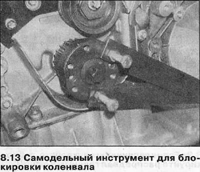
- A) Use the tool described in point 2, screwing its bolts into the opposite holes to mount the pulley (see illustration).
- b) On manual transmission models, have an assistant select the highest gear and depress the brake pedal firmly.
- V) If the engine or transmission unit has been removed from the vehicle, block the flywheel/drive plate (see chapter 15).
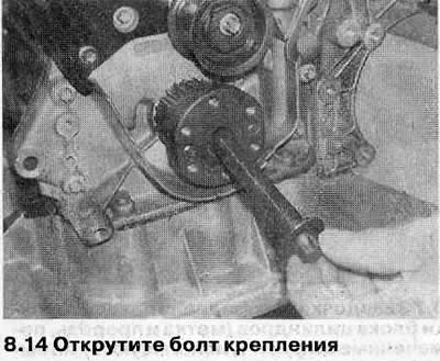
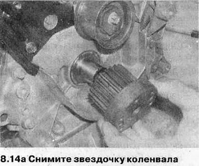
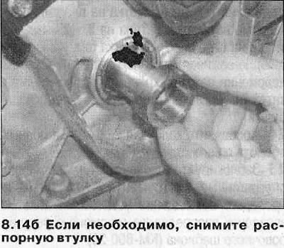
14. Turn off a bolt of fastening and remove an asterisk of a crankshaft. Discard the bolt - it must be replaced. If necessary, remove the spacer from the stuffing box. If the outer surface of the sleeve is damaged, the component must be replaced (see illustrations).
Installation
15. Before installing, inspect the oil seal for damage and leaks and replace if necessary (see chapter 16).
16. Install spacer (where filmed) onto the crankshaft, taking care not to damage the sealing lip of the oil seal.
17. Align the sprocket with the crankshaft groove and install it in working position with the flange facing out. Install a new mounting bolt.
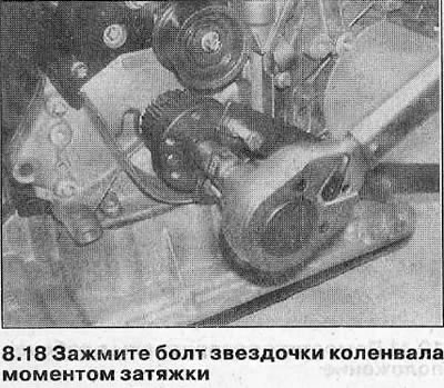
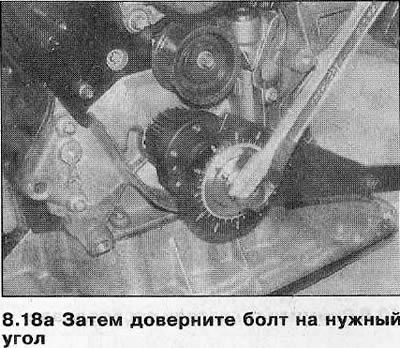
18. Block the crankshaft using the same method used in removal and tighten the sprocket mounting bolt to the required torque (see specs). Sequentially tighten the bolt to the desired angle (see specs) with socket and extension rod. It is recommended to use an angle gauge for this to ensure accuracy (see illustrations). If a template is not available, apply alignment marks to the bolt head and flywheel to help ensure the bolt is rotated to the correct angle.
19. Install the toothed belt as described in Chapter 7.
Tensioner Pulley/Upper Guide Pulley Assembly
Attention! The tensioner pulley/upper idler pulley must be replaced as an assembly.
Removing
20. Remove the toothed drive belt as described in Chapter 7.
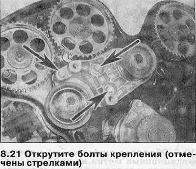
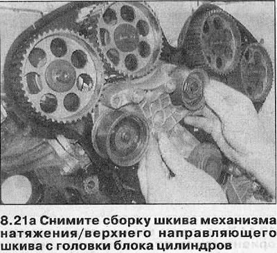
21. Remove the bolts securing the tensioner support plate to the cylinder head and remove the assembly from the engine (see illustrations).
Installation
22. Install the assembly on the cylinder head and tighten the fastening bolts with a tightening force regulated specifications.
23. Install the toothed belt as described in Chapter 7. If a new tensioner assembly is installed, replace the toothed belt as well.
Lower guide pulley
Removing
24. Remove the toothed belt as described in Chapter 7.
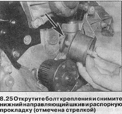
25. Loosen the mounting bolt and remove the lower guide pulley and its spacer from the engine (see illustration).
Installation
26. Position the spacer behind the idler pulley, then install the pulley mounting bolt.
27. Install the toothed belt as described in Chapter 7.
Visitor comments