
Removing
Attention! Allow the engine to cool before removing the cylinder head. When installing, use new head bolts.
1. Remove the battery (see related section).
Attention! On models with anti-theft system Opel (ATWS), the negative wire must be separated from the battery terminal within 15 seconds after the ignition is turned off, otherwise the alarm will sound.
2. Remove wiper arms and water deflector panel (see related section).
3. Remove the complete intake manifold assembly, including its flange (see related section).
4. Drain the cooling system and remove the spark plugs as described in Section 1.
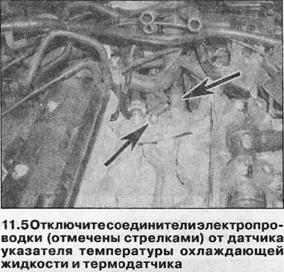
5. Disconnect the wiring connectors from the coolant temperature gauge sensor and engine management system temperature sensor that are screwed into the cooling system outlet pipe assembly (see illustration).
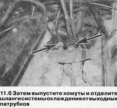
6. Loosen the mounting clamps and separate the cooling system hoses from the nozzles (see illustration).
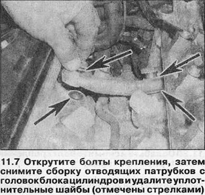
7. Turn off bolts of fastening and remove assembly of taking-away branch pipes from heads of the block of cylinders. Remove o-rings and discard - they must be replaced (see illustration).
8. Remove the toothed belt as described in Chapter 7.
9. Remove the camshaft sprockets, tensioner pulley/top timing belt guide pulley assembly and bottom guide pulley (see chapter 8).
10. Remove the water pump as described in Section 3.
11. Turn off bolts of fastening and remove an internal cover of a gear belt (see chapter 6).
Left cylinder head
12. Remove the valve cover as described in Chapter 4.
13. Disconnect the wiring connector and high-voltage spark plug wires of the right cylinder head from the ignition control module so that the latter can be removed with the head. Also remove the grounding bolts from the rear of the left cylinder head.
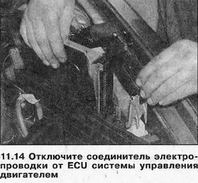
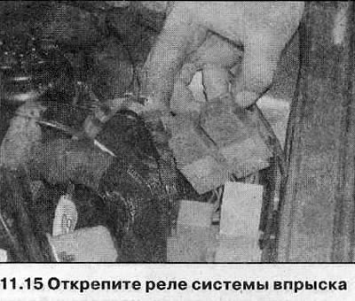
14. Remove a cover of a box of the relay in the left corner of a motor compartment. Raise the ECM (ECU), then release the retaining bracket and disconnect the electrical wiring connector (see related section) (see illustration). The ECU can be left in the working position in the box.
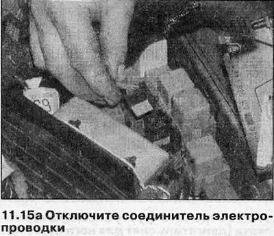
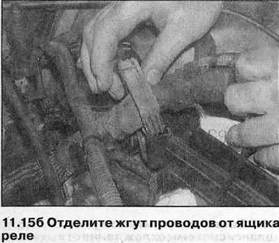
15. Follow the wiring harness from the left cylinder head to the relay box in the engine compartment. Release the injection relay connectors from the box, then disconnect the harness connector and release the o-ring (see illustrations).
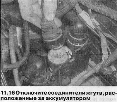
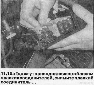
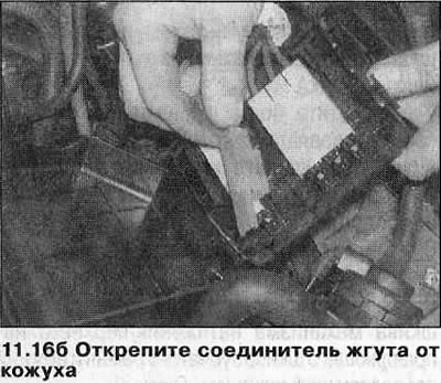
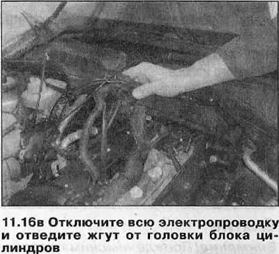
16. Disconnect the harness connectors located behind the battery, then the connectors for the camshaft position sensor and knock sensor of the left cylinder head. Separate the auxiliary harness connectors from the positive battery terminal and move the harness away from the cylinder head. On some models, instead of the battery terminal, the harness is connected to the fuse block. In this case, remove the fusible connector and unfasten the wiring from the unit (see illustrations).
17. Remove the left front exhaust pipe (see related section).
18. Remove the power steering pump (see related section).
19. Loosen the clamp and separate the upper radiator hose from the tube on the front side of the left cylinder head.
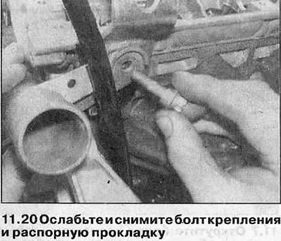
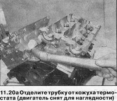
20. Loosen the bolt and spacer securing the coolant pipe and engine mounting lug to the cylinder head and remove the mounting lug. Move the tube to the left to separate it from the thermostat housing, then remove the tube (see illustrations). Remove the o-rings from the inner end of the tube and discard them - they must be replaced.
21. Remove the dipstick for measuring the oil level, then unfasten the dipstick tube from the cylinder block and remove it from the engine. Discard the tube O-rings - they must be replaced.
22. Remove exhaust camshaft (see related section).
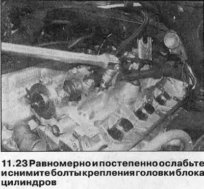
23. Working in reverse order of their tightening (see illustration 11.41), gradually loosen the cylinder head bolts (a quarter turn in one go), then unscrew the bolts by hand (see illustration). Remove each bolt and washer one by one.
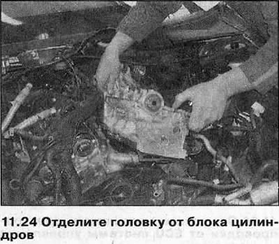
24. Lift the head off the cylinder block (see illustration). If necessary, tap the head gently with a mallet to separate it. In no case do not press the head from the cylinder block, this will damage the contact surfaces. If the alignment pins are loose, note their location and remove for safekeeping.
25. Remove the cylinder head gasket - it must be replaced.
Right cylinder head
26. Place a suitable container under the oil filter. Unscrew the filter using the special tool and drain the oil into a container. Replace filter.
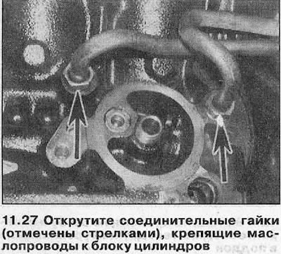
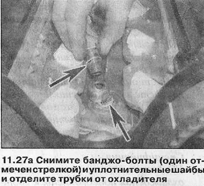
27. Unscrew the union nuts securing the engine oil cooler tubes to the cylinder block, then unscrew the banjo bolts securing the tubes to the cooler. Remove the sealing washers from each side of the couplings and slide the tubes back (see illustrations).
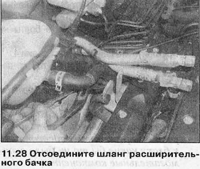
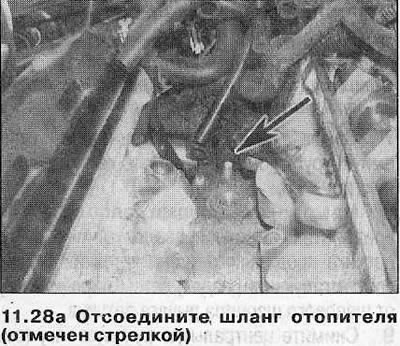
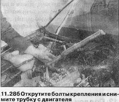
28. Release the mounting clamps and separate the lower radiator hose, expansion tank hose and heater hose from the tube running along the right side of the engine. Loosen the mounting bolts, then remove the tube from the engine. Discard the O-ring - it must be replaced (see illustrations).
29. Remove the right front exhaust pipe (see related section).
30. Remove exhaust camshaft (see chapter 10).
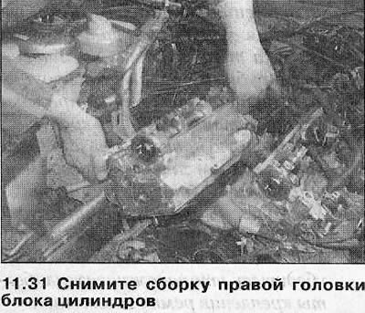
31. Remove the cylinder head as described in paragraphs 23-25 (see illustration).
Preparing for installation
32. Clean the mating surfaces of the head and cylinder block. Use a soft scraper to remove all traces of gasket and carbon deposits, and clean the piston heads as well. Be especially careful with the aluminum cylinder head as the soft metal is easily damaged. Keep dirt out of the oil and water passages - grains of soot can block the oil supply to the camshaft or crankshaft bearings. Use masking tape and paper to cover the water and oil holes and the bolt holes in the cylinder block. To prevent grains from falling into the gap between the cylinder wall and the piston, apply a little grease to this area. After cleaning the piston, turn the crankshaft so that this piston moves down and remove the grease from the cylinder with a clean rag.
33. Check the block and head for nicks, deep scratches and other damage. Small irregularities can be carefully filed off. More serious damage can be repaired by regrinding, but this work should be left to a specialist.
34. If necessary, check the cylinder head for deformation with a ruler. See Section 2C, if it is needed.
35. Make sure that the holes for the cylinder head bolts in the crankcase are clean and remove oil from them using a syringe or sponge. If liquid or oil remains in the holes, the hydraulic pressure that will build up when the bolts are tightened will cause the block to crack.
Installation
Left cylinder head
36. Make sure the crankshaft is still at approximately 60°BTDC and wipe the mating surfaces of the head and block.
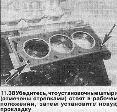
37. Make sure the alignment pins are in the working position.
38. Install a new head gasket on the cylinder block with a mark «OBEN» (or «TOR») up and towards the front of the engine (see illustration).
39. Carefully install the cylinder head (with exhaust manifold), guiding it along the pins.
40. Lightly lubricate the threads and heads of the new cylinder head bolts with engine oil, then carefully insert them into position and tighten only by hand so far.
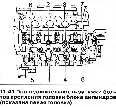
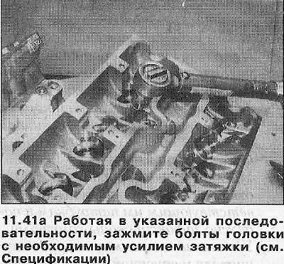
41. Working in the sequence shown, gradually tighten all the cylinder head bolts to the torque (see illustrations).
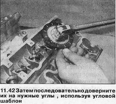
42. In the same sequence, tighten each bolt to the desired angle (see specs). It is recommended to use an angle gauge for this to ensure accuracy (see illustration).
43. In the same way, tighten the bolts to the desired angle (see specs).
44. Repeat this step for Stage 4.
45. Finally, tighten the bolts in the same sequence by an angle.
46. Next, install in the reverse order of removal, paying attention to the following:
- A) If the right cylinder head has also been removed, install it before attaching any accessories to the block.
- b) Install new O-rings on the dipstick tube and thermostat housing tube. Make sure that the tubes and mounting eye are each placed in their original place, install the mounting bolt and spacer and tighten the bolt with the tightening torque specified in the Specifications.
- V) Make sure the engine wiring harness is routed correctly and all connectors are connected. Also make sure that the ground strap mounting bolts are securely tightened.
- G) Install the camshaft, toothed drive belt and related components as described in Chapters 6-10.
- d) Use new O-rings when installing the cooling system outlet pipes to the cylinder heads and tighten the mounting bolts to the specified torque.
- e) Make sure that all hoses of the cooling system are connected to their respective nozzles and securely fixed with clamps.
- and) Install the exhaust pipe and intake manifold (see related section).
- h) Finally, fill the cooling system and the reservoir of the power steering hydraulic system (see related section).
Right cylinder head
47. Install the head as described in paragraphs 36-45, remembering that the label of its gasket («OWEN» or «TOR») must face up and towards the rear of the engine.
48. Next, install in the reverse order of removal, paying attention to the following:
- A) If the left cylinder head was also removed, install it before attaching any accessories to the block.
- b) Install a new O-ring on the coolant tube and tighten the tube bolts securely.
- V) Install new sealing washers on the engine oil cooler couplings and tighten the nuts and bolts of the couplings with a torque specified specifications.
- G) Install the camshaft, toothed drive belt and related components as described in Chapters 6-10.
- d) When installing the cooling system outlet pipes on the cylinder heads, use new O-rings and tighten the fastening bolts with a torque specified specifications.
- e) Make sure that all hoses of the cooling system are connected to their respective nozzles and securely fixed with clamps.
- and) Install the exhaust pipe and intake manifold (see related section).
- h) Install a new oil filter and fill the cooling system (see related section).
- And) Finally, check the engine oil level (see related section).
Visitor comments