


Contents: Single camshaft engines ⬇ Twin Cam Engines ⬇
Single camshaft engines
Removal
Note: The engine must be cold when removing the cylinder head.
Disconnect the negative terminal from the battery.
Drain the coolant from the cooling system.
Disconnect the exhaust pipe from the manifold.
The cylinder head can be removed together with the pipes, or the pipes can be removed from the head before removal (chapter 4).
If the cylinder head must be removed together with the lines, disconnect all hoses, tubes and wiring from the intake manifold (chapter 4). On carbureted engines, disconnect the hot air hose from the exhaust manifold housing.
Disconnect the air cleaner line.
Disconnect the hose at the camshaft cover. On fuel-injected models, remove the wiring bolt.
For 1.4 and 1.6 L engines, disconnect the breather hose from the branch pipe.
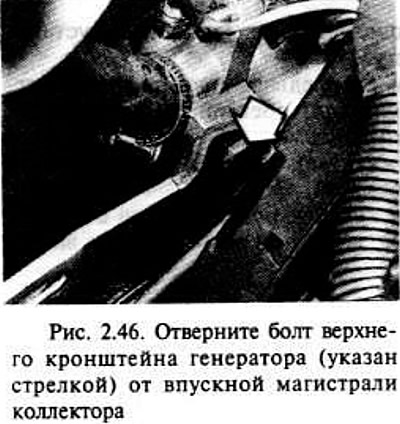
Loosen the generator mount, then remove the upper bracket from the intake manifold.
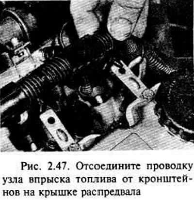
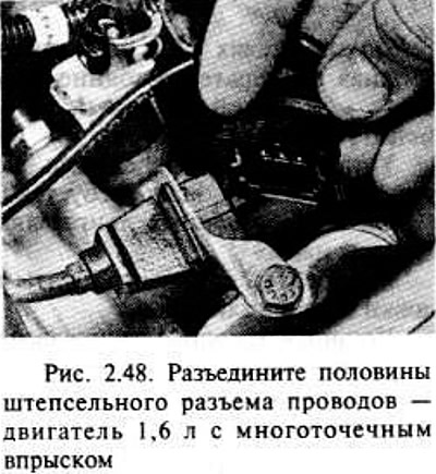
Disconnect the fuel injection unit wiring from the brackets on the camshaft cover if necessary, then disconnect the plug connector.
Make sure all hoses, tubes and wires are disconnected, then unscrew the nuts, marking the location of the brackets (for example, a bracket for lifting the engine), connected to the cylinder head studs, and separate the intake manifold from the cylinder head.
Remove the intake manifold gasket. If necessary, remove the exhaust manifold (chapter 4).
Remove the camshaft sprocket, unscrew the two bolts of the upper rear cover of the distributor belt.
Disconnect the high tension wires from the spark plugs and ignition coil, labeling them to make installation easier.
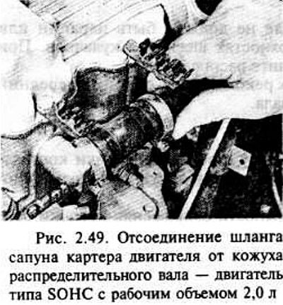
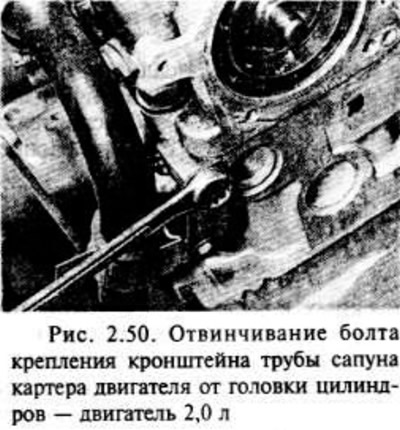
Disconnect the breather hose on 1.8 and 2.0 L engines, unscrew the breather bracket bolt on the cylinder head.
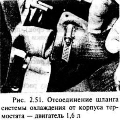
Disconnect the coolant hose from the thermostat housing.
On carbureted engines, disconnect the hoses from the fuel pump. Clamp the ends of the hoses to prevent fuel leakage.
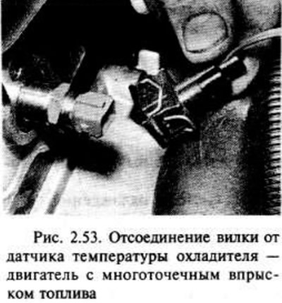
Disconnect the wiring plug from the system coolant temperature sensor if necessary. Make sure all hoses, tubes and wires are disconnected.
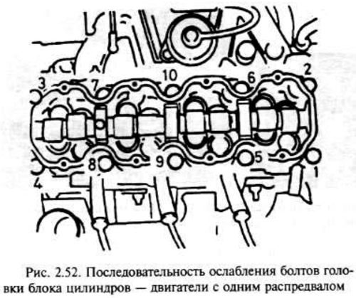
In the sequence shown in the figure, loosen all cylinder head bolts first by a quarter of a turn, then by half a turn, and finally completely unscrew them.
Separate the camshaft housing from the cylinder head. If necessary, gently tap the housing with a soft-sided hammer, but do not lever it up against the mating surfaces.
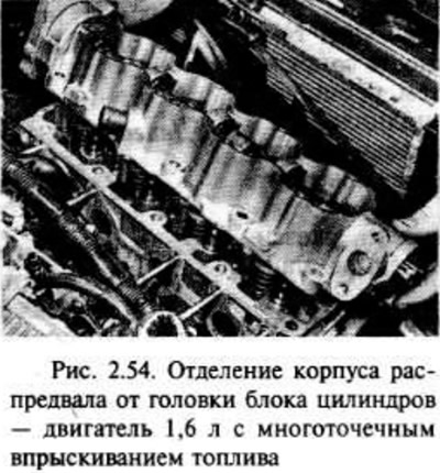
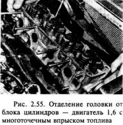
Disconnect the head from the cylinder block in the same way.
Remove the valve rocker arms and gaskets, noting their order for subsequent installation.
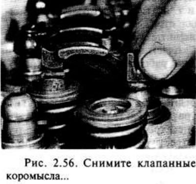
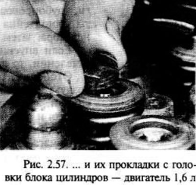
Remove the hydraulic valve lifters from the cylinder head and arrange them in such a way that they can be later installed in their original position.
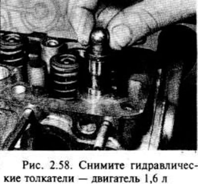
Remove the cylinder head gasket.
Installation
Clean the mating surfaces of the cylinder head and block, the camshaft housing and the cylinder head, carefully scraping off dirt with a scraper. Do not damage these parts, made of light alloy, as they can be easily scratched.
Cover the cooling system vents and other openings with tape or rags to prevent dirt and grime from getting in. Wipe off any remaining oil from the bolt holes; if oil remains in the holes, hydraulic pressure can cause cracks in the block when the bolts are tightened.
Begin installing the cylinder head with the new head gasket on the block so that the word OBEN or TOP (TOP) is visible from the top, as shown in the figure.
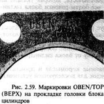
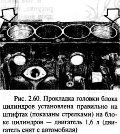
Before installing hydraulic valve lifters, we recommend disassembling them and cleaning them (part B of this chapter).
Install the hydraulic valve lifters, gaskets and rocker arms into the cylinder head. Generously lubricate the tappet bores with oil. Lightly lubricate the contact end surfaces of the valve lifters, support gaskets and rocker arms with molybdenum disulfide grease.
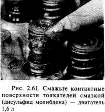
Temporarily install the crankshaft sprocket, making sure that the timing marks are in position with piston No.1 at TDC.
Apply sealant (vauxhall/Opel N 15 03 166 or equivalent) onto the mating surface of the cylinder head, then install the camshaft housing and cylinder head.
Install the new cylinder head bolts, making sure the washers are in place. Tighten the bolts by hand as much as possible.
Tighten the bolts in the sequence shown in the illustration. Tighten the bolts in four stages as required by specification.
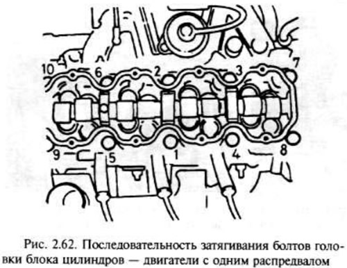
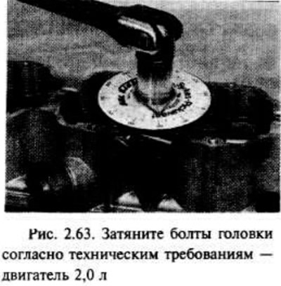
Installation is carried out in reverse order, taking into account the following steps.
Make sure the high tension wires are connected to the spark plugs.
Install the camshaft sprocket.
Install the manifold on the cylinder head if required, replacing the gaskets with new ones.
Connect the exhaust manifold pipe using a new gasket.
Install the upper generator bracket on the intake manifold, adjust the generator belt tension.
Fill the cooling system with coolant.
After starting the engine, check for signs of leakage.
Once the engine has reached normal operating temperature, check and, if necessary, adjust the idle speed and mixture quality. Finally, fully tighten the cylinder head bolts (fifth stage).
Twin Cam Engines
Removal the cylinder head
Disconnect the negative battery terminal.
Drain the coolant from the cooling system.
Disconnect the exhaust system (chapter 4).
The cylinder head can be removed together with the intake manifold, or it can be disconnected.
If the cylinder head is removed together with the intake manifold, disconnect all hoses, lines, etc. (chapter 4) and unscrew the manifold bracket bolts. Loosen the generator mount, then unscrew the upper bolts.
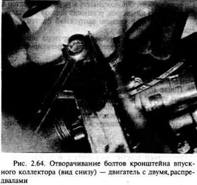
If the intake manifold remains in the engine compartment, the procedure will be as follows.
Disconnect the connector plug from the air flow meter and the breather hose from the throttle body, then disconnect the air cleaner line and remove the air flow meter (chapter 4).
Disconnect the end of the throttle cable from the lever, then remove the intake manifold bracket by unscrewing the bolts.
Unscrew the two nuts of the wires to the "ground" of the fuel distribution line (one at each end), and disconnect all three wires to ground.
Disconnect the wiring connector plug from the throttle position sensor.
Pull the housing up and disconnect the wiring from the injectors.
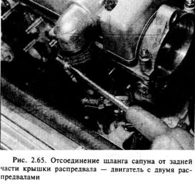
Disconnect the two breather hoses from the rear of the camshaft cover.
After loosening the fastening, unscrew the bolts at the top of the generator. Unscrew the collector bracket bolts.
Check that all hoses, pipes and wiring are disconnected, then remove the intake manifold from the cylinder head by unscrewing the nuts.
Remove the manifold gasket from the cylinder head.)
Remove the camshaft sprocket.
Remove the timing belt tensioner and idler pulley. Unscrew the upper and middle fasteners of the outer belt cover (the top clamp simply unscrews, the middle one is secured with a bolt). Unscrew the two bolts of the upper rear belt cover.
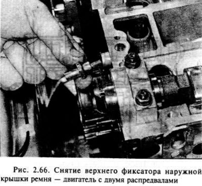
Disconnect the distributor cap and high tension wires (chapter 5).
Disconnect the ignition distributor wire connector.
Disconnect the coolant hoses from the left side of the cylinder head.
Loosen the breather bracket bolt on the cylinder head.
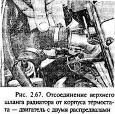
Disconnect the upper radiator hose from the thermostat housing and the wiring from the temperature sensors in the cooling system (both in the thermostat housing).
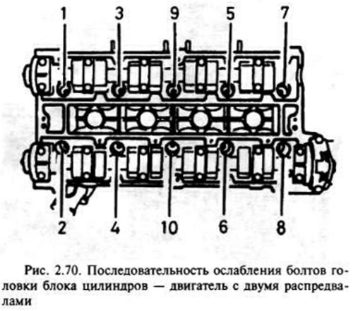
Using a socket wrench or Torx sleeve, perform the operations in the sequence shown in Fig. 2.70: loosen all bolts by a quarter, then by half a turn, and finally loosen and unscrew the bolts completely.
Lift the cylinder head. If necessary, tap it gently with a soft-shell hammer. However, it should not be pryed up on the mating surface. Remember that the head is located on the dowel pins. Remove the gasket.
Installation
Remove dirt from the mating surfaces of the head and cylinder block by scraping it gently. Be careful not to damage the head, it is made of light alloy and is easily scratched. Cover the cooling system openings, etc. with adhesive tape or rags to prevent dirt from getting into them. Wipe off all traces of oil from the bolt holes; if oil remains, hydraulic pressure may cause cracks in the block when installing the bolts.
Start the installation by placing a new pad on the block so that the word OBEN or TOR (TOP) is on top.
After thoroughly cleaning the mating surfaces, position the head on the cylinder block so that the installation fonts enter the holes.
Temporarily install the crankshaft pulley and camshaft sprockets; make sure that piston No.1 is installed in VM 1.
Install new cylinder head bolts with washers and tighten the bolts by hand as much as possible.
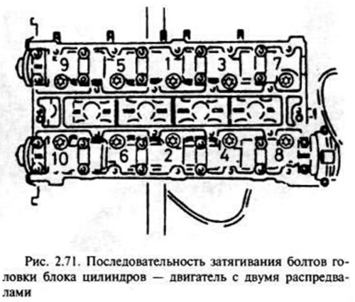
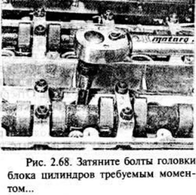
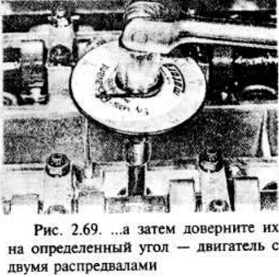
Tighten the bolts in the sequence shown in the illustration. Tighten the bolts in four steps according to specification.
Original source is on the website: OPELBOOK.ru
Further installation is carried out in the reverse order of removal, taking into account the following.
Install the belt tensioner and idle pulley, camshaft sprockets and a new belt, adjusting its tension.
If necessary, connect the intake manifold to the cylinder head using a new gasket.
Connect the exhaust section using a new gasket.
Tightening the generator mounting bolts on the intake manifold (where required), adjust the alternator belt tension.
Fill the cooling system with coolant.
Check that all hoses, pipes and wiring are connected.
After starting the engine, check for signs of leaks.
After the engine has reached normal operating temperature, perform the final tightening of the cylinder head bolts according to step five.
Visitor comments