


Contents: Engine Z16XE/Z18XE ⬇ Engines Z22YH/Z22SE/Z20NET ⬇ Z32SE Engine ⬇ Z19DT(H) Engines ⬇ Engines Y20DTH/Y22DTR ⬇ Y30DT Engine ⬇
Engine Z16XE/Z18XE
1. Disconnect the cable from the negative terminal of the battery.
2. Raise the car on a lift, drain the engine oil from the crankcase. Before screwing in the drain plug, do not forget to replace the gasket.
3. Remove the multi-rib belt cover and exhaust system.
4. Disconnect the engine oil level sensor, remove the 2 rubber plugs and unscrew the mounting bolts shown in the accompanying illustration and the 12 oil pan mounting bolts. Using a suitable tool, pry off the oil pan.
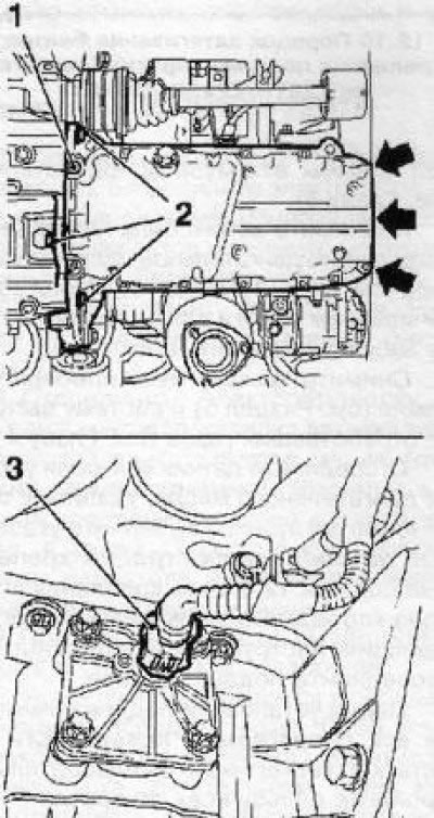
12.4 Oil pan (z18XE engine) - the arrows indicate the bolts that secure the pan to the oil pump: 1. Rubber plugs; 2. Transmission mounting bolts; 3. Engine oil level sensor wiring connector
5. Before installing the tray, clean all mating surfaces from any remaining sealant and pre-thread all holes.
6. Apply a bead of sealant (gray color) thickness 2.5-3.5 mm on the surfaces indicated in the accompanying illustration and install the tray in place.
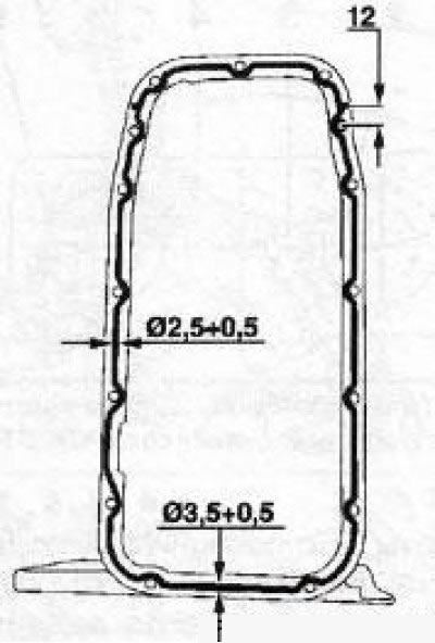
12.6 Apply fresh sealant before installing the tray (z18XE engine)
Attention! Installation must be completed no later than 10 minutes after applying the sealant!
7. Installation of the remaining components is carried out in the reverse order of their removal.
Engines Z22YH/Z22SE/Z20NET
8. Disconnect the wire from the negative terminal of the battery, unscrew the mounting bolt and remove the engine oil dipstick tube.
9. Raise the vehicle on a lift and remove the multi-rib belt.
10. Drain the engine oil. Before screwing in the drain plug, be sure to replace the gasket.
11. Remove 3 mounting bolts and remove the compressor, disconnect the wiring of the engine oil level control sensor.
12. Unscrew the mounting bolts (see illustration) oil pan, use a suitable tool, pry the pan at the points indicated by the arrows and separate it from the engine block.
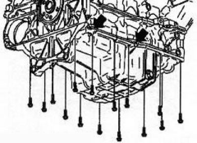
12.12 Fastening the oil pan (engines Z22YH/Z22SE/Z20NET)
13. Before installing the tray, clean all mating surfaces from any remaining sealant and pre-thread all holes.
14. Apply a bead of sealant (gray color) thickness 2.0-2.5 mm on the surfaces indicated in the accompanying illustration and install the tray in place.
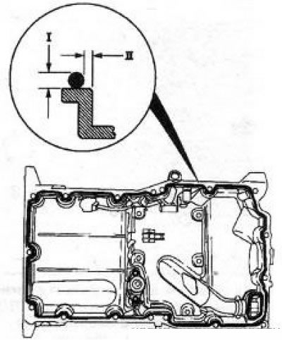
12.14 Before installing the tray, apply sealant to its mating surfaces (engines Z22YH/ Z22SE/Z20NET): Size I - 2.0-2.5 mm; Size II - 0.5-1.5 mm
Attention! Installation must be completed no later than 10 minutes after applying the sealant!
15. Tighten the 15 bolts (see illustration) pallet fastening force 23 Nm, and then 2 bolts securing the pan to the transmission with force 40 Nm.
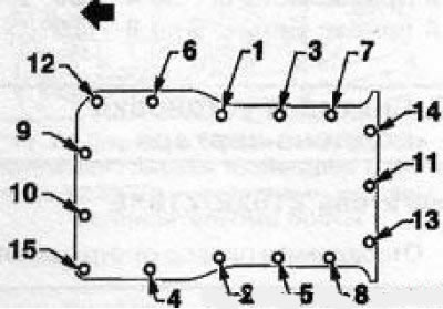
12.15 Tightening procedure for oil pan mounting bolts (engines Z22YH/Z22SE/Z20NET): 1. Engine block mounting bolts; 2. Engine oil level control sensor; 3. Transmission mounting bolts
16. Installation of the remaining components is carried out in the reverse order of their removal.
Z32SE Engine
17. Raise the vehicle on a lift and remove the multi-rib belt cover.
18. Remove the exhaust system.
19. Drain the engine oil from the crankcase. Before screwing in the drain plug, do not forget to replace the gasket.
20. Disconnect the sensor wiring (see accompanying illustration) check the engine oil level, unscrew the 3 bolts securing the pan to the transmission, and the 17 bolts securing it to the block.
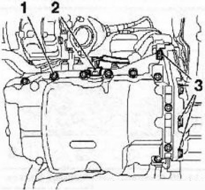
12.20 Fastening the oil pan (z32SE engine)
21. Remove the pan, being careful not to damage the mating surfaces. At the service station, the KM device is used for this purposeJ-37228.
22. Before installing the tray, clean all mating surfaces from any remaining sealant and pre-thread all holes.
23. Apply a bead of sealant (gray color) thickness 3.0-3.5 mm on the surfaces indicated in the accompanying illustration and install the tray in place.
Attention! Installation must be completed no later than 10 minutes after applying the sealant!
Tighten the bolts to the required torque.
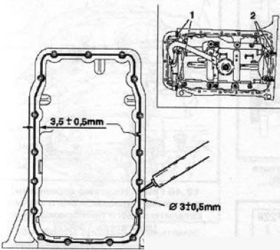
12.23 Before installing the tray, apply sealant to its mating surfaces (z32SE engine): 1. Joints with the oil pump body; 2. Cylinder block joints
24. Installation of the remaining components is carried out in the reverse order of their removal.
Z19DT(H) Engines
25. Remove the bolt and disconnect the upper part of the engine oil dipstick tube.
26. Remove the intermediate drive shaft, cover the transmission hole with a suitable plug.
27. Remove the front section of the exhaust system, unscrew the 3 bolts and remove the catalytic converter mounting bracket.
28. Loosen the 4 crankshaft pulley bolts, remove the multi-rib belt and remove the pulley.
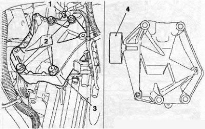
12.29 Bolts (2) for fastening the bracket (3) of the compressor (engine z19DT): 1. Electrical wiring connector; 4. Guide roller
29. Disconnect the compressor wiring, remove the 3 bolts and remove the compressor, then remove the bolts (see illustration) compressor bracket mounts and remove it together with the guide roller.
30. Drain the engine oil from the crankcase, disconnect the lower part of the engine oil dipstick tube and remove the tube.
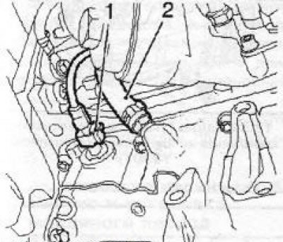
12.31 Sensor (1) for monitoring engine oil level and return hose (2) of the lubrication system (z19DT engine)
31. Disconnect the electrical wiring from the sensor (see illustration) to check the engine oil level, remove the engine lubrication system return hose.
32. Turning the crankshaft in the direction of engine rotation (clockwise) install the engine flywheel so that the bolts securing the oil pan to the transmission can be unscrewed through the holes in the flywheel. I use a special device EN-46794, first unscrew one bolt, turn the crankshaft again and unscrew the second bolt.
33. Using a device EN47631 unscrew the 2 bolts securing the pan on the timing drive side.
34. Unscrew the remaining 10 oil pan mounting bolts and separate it from the block. Unscrew 2 bolts (see illustration) oil intake mounts and remove the pan together with the oil intake from the engine.
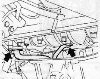
12.34 Bolts (indicated by arrows) oil intake mounts (z19DT engine)
35. Installation is carried out in the reverse order of removal. Do not forget to replace all gaskets and seals.
Engines Y20DTH/Y22DTR
36. Remove the engine cover, disconnect the EGR valve wiring and remove the oil filter.
37. Remove the crankcase guard and drain the engine oil.
38 Disconnect the wiring from the level control sensor and engine oil temperature sensor (see illustration). Remove the 4 oil pan bolts to the transmission, then the 17 oil pan bolts to the engine block and remove the oil pan. Remove the oil pan gasket.
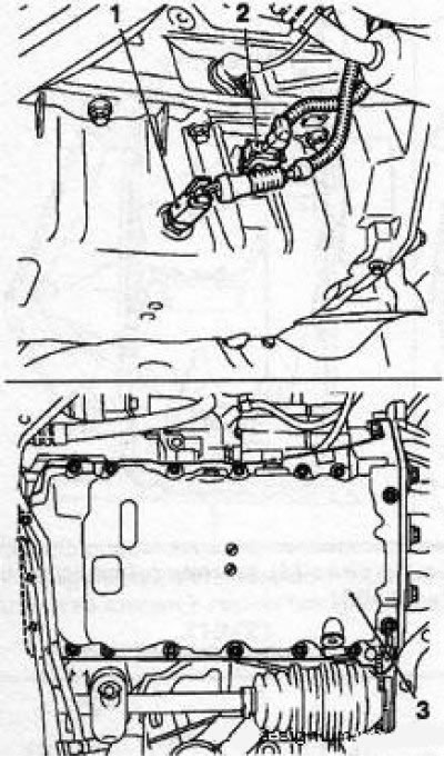
12.38 Fastening of the oil pan (3) (y20DTH/Y22DTR engines): 1. Engine oil temperature sensor; 2. Engine oil level control sensor
39. If necessary, unscrew the 4 bolts and remove the oil intake.
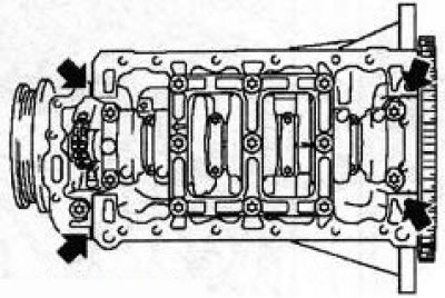
12.40 Places to apply sealant (y20DTH/Y22DTR engines)
40. Installation is performed in the reverse order of removal. Before installing the pan, apply sealant to the joints of the engine block (see illustration). Don't forget to replace the sealing gaskets.
Y30DT Engine
41. Remove the subframe.
42. Remove the engine oil dipstick, remove the battery with the pan, disconnect the upper part of the turbocharger air duct and move the air duct to the side.
43. Remove the expansion tank with the hose. Release the engine wiring harness and move it to the side, freeing access to the turbocharger heat shield. Unscrew the 5 bolts/screws and remove the heat shield.
44. Remove the 3 bolts to disconnect the front section of the exhaust system, remove the engine oil dipstick tube, raise the vehicle on a lift and drain the engine oil.
45. Remove the 2 bolts and catalytic converter mounting bracket. Remove the front section of the exhaust system.
46. Loosen the 2 nuts (see illustration) and remove the catalytic converter heat shield.
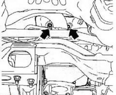
12.46 Nuts (indicated by arrows) fastenings of the heat shield of the catalytic converter (y30DT engine)
47. Remove the intermediate drive shaft and shaft bracket.
48. Unscrew 16 bolts and 2 nuts and remove using the KM- toolJ-37228 (see illustration) the lower part of the oil pan.
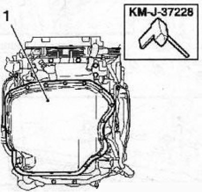
12.48 Lower part (1) of oil pan (y30DT engine)
49. Remove the engine oil dipstick tube. Disconnect the wiring for the level control sensor and engine oil temperature sensor.
50. Loosen the mounting clamps and remove the crankcase ventilation hose.
51. Remove the front engine mount multi-rib belt.
52. Disconnect the compressor wiring (see illustration), unscrew 3 bolts and remove the compressor.
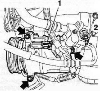
12.52 Bolts (indicated by arrows) compressor mounts (y30DT engine): 1, 2 Electrical wiring connectors
53. Unscrew the 10 bolts securing the upper part of the pan and remove it.
Note: The bolts are of different lengths. Remember or mark their installation locations.
54. When replacing the pallet, it is necessary to remove all removable elements from the old pallet and install them on the new pallet.
55. Before installing the tray, clean all mating surfaces from any remaining sealant and pre-thread all holes.
56. Apply a bead of sealant (gray color) thickness 3.0-4.0 mm on the surfaces indicated in the accompanying illustrations and install the tray in place
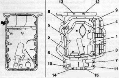
12.56a Places (indicated by an arrow) application of sealant and the order of tightening the fastening of the upper part of the oil pan (y30DT engine)
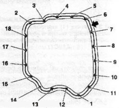
12.56b Places (indicated by an arrow) application of sealant and the order of tightening the fastening of the lower part of the oil pan (y30DT engine)
Attention! Installation must be completed no later than 10 minutes after applying the sealant! Tighten the bolts and nuts of the upper and lower parts of the tray with the required force in the specified order, short and long bolts must be installed in their places.
57. Installation of the remaining components is carried out in the reverse order of their removal.
Visitor comments