
OpelBook.ru
Cars AvtoVAZ Cars Mitsubishi Cars BMW Cars Mercedes Cars Nissan Cars Toyota Cars Chevrolet
English Русский
Български
Беларускі
Український
Српски
Hrvatski
Română
Polski
Slovenský
Magyar
 |  Sitemap  |  Contacts  |    


Main Astra Corsa Insignia Kadett Omega Vectra Zafira Others Articles
Astra F (1991-1998, petrol) Astra G (1998-2004, petrol) Astra G (1998-2004) Astra H (2004-2009) Astra J (2009-2015, petrol)
  • Main
  • Astra
  • Astra G
  • Power unit
  • Injection system (diesel)
  • Checking and adjusting fuel injection timing settings

Checking and adjusting fuel injection timing settings (Opel Astra G)

            0

Contents: Engines 1.7L SOHC ⬇ Engines 1.7L DOHC ⬇ 2.0L Engines ⬇
Prevent dirt and moisture from getting inside the power supply system!


Some adjustment elements and pump connectors may be sealed by the manufacturer by painting over or installing wire protection, the removal of which will result in a breach of warranty.


Engines 1.7L SOHC


The fuel injection moment is calculated by the ECM based on the analysis of information coming from various sensors. The check can only be performed using special diagnostic equipment and its implementation should be entrusted to car service specialists.

Engines 1.7L DOHC


Although the injection timing on these engines is set by the ECM, replacing the injection pump entails the need to set the base values of the injection timing. A full check can only be carried out using special diagnostic equipment and should be entrusted to car service specialists.

1. If you have not already done so, remove the air intake duct with air cleaner (see Removal and installation air intake tract components). Also remove the upper timing belt cover (see Chapter Engine).

Original posted on the website [www.opelbook.ru]

2. Unscrew the mounting bolts and remove the fuel injector pipes. The authors of this Manual believe that it is necessary to unscrew the mounting bolt (see Chapter Engine) and move the oil cooler assembly back to provide adequate access to the fuel injection pump - be prepared to collect any spilled fuel.

3. Bring the crankshaft to the position 45° before TDC of the piston of the first cylinder (see Chapter Engine).


4. Unscrew the central bleed screw located between the connections of the four fuel pipes at the rear of the high-pressure fuel pump.
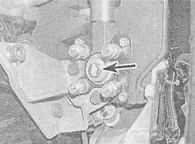
4. Unscrew the central bleed screw located between the connections of the four fuel pipes at the…


5. Screw the nozzle into the back of the pump and install a plunger type dial gauge, these tools (Opel KM-798) should be available to every diesel operator. Zero the gauge at the plunger stroke position and tighten the lock nut/nozzle bolt securely.
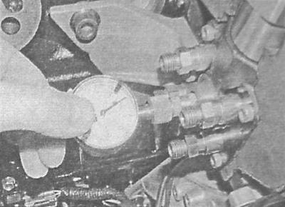
5. Screw the nozzle into the back of the pump and install a plunger type dial gauge, these tools…


6. Slowly rotate the crankshaft in both directions and use the meter to determine the bottom stroke point (BDC). Once you have achieved the desired result, reset the meter to zero.

7. Slowly turning the crankshaft clockwise, align the timing mark on the crankshaft pulley with the counter indicator (TDC position of the end of the compression stroke of the piston of the first cylinder - see Chapter Engine).


8. Check the plunger stroke value taken with the measuring device against the requirements of the Specifications. If necessary, loosen the front nuts and rear bolts of the pump mount and, smoothly turning the pump body, achieve the required result. Turning the pump towards the engine leads to a decrease in readings, away from the engine - to an increase. Having achieved a satisfactory result, tighten the front nuts and rear bolts with the required force.

9. Turn the crankshaft one or three quarters of a turn in the normal direction (clockwise), set the pump plunger to BDC (see above p.7), then zero the meter.

10. Slowly rotate the crankshaft clockwise until the timing mark on its pulley aligns with the pointer (TDC of pistons of 1st and 4th cylinders). Repeat the check of the injection pump plunger stroke value.

11. If adjustment is required, loosen the pump mounting nuts and bolts and repeat the procedure (see above pp. 9-10).

12. Having determined the exact value of the pump plunger stroke (and, therefore, the injection moment) unscrew the nozzle and remove the meter.

13. Install the center bleed screw.

14. Restore the original fuel line connection - make sure the union nuts are tightened to the required torque. If removed, reinstall the oil cooler housing and tighten its mounting bolt.

15. Install the upper timing cover, air cleaner and intake air ducts.

16. The fuel system is "primed" automatically, although the engine start procedure may take a little longer than usual. Check the engine for signs of developing leaks.


2.0L Engines


The fuel injection moment is calculated by the ECM based on the analysis of information coming from various sensors. The check can only be performed using special diagnostic equipment and its implementation should be entrusted to car service specialists.


This article is available at russian, bulgarian, belarusian, ukrainian, serbian, croatian, romanian, polish, slovak, hungarian
Checking the article: Pavlovsky Nikolay

Share information:

Previous articles
Opel Astra G: Injection system (diesel)
Next articles

Checking and adjusting maximum engine speed
Diesel engine injection and turbocharging systems
Removal and installation of electrical components of the power supply system
Signals and voltages at the control module terminals
Removal and installation of fuel injection pump
Removal and installation fuel injectors
Removal and installation a turbocharger
Removal and installation the intermediate cooler (intercooler)


See similar ones from other Opel car manuals:
▶ Checking and adjusting fuel injection timing settings Opel Corsa B (1993-2000)
▶ Checking and adjusting the GM «Multec SPI» fuel injection… Opel Kadett E (1984-1995)
▶ Fuel injection system throttle switch — checking and… Opel Omega A (1986-1993)
▶ Checking the fuel injection timing Opel Vectra B (1995-2002)
▶ Timing Belt — Checking Condition, Adjusting Tension and… Opel Zafira A (1999-2005, petrol)
Link to this page in different formats

Visitor comments


No comments yet


How much will 28 + 39 =


Astra J (2009-2015, petrol) 
  • General information
  • Vehicle device
  • User manual
  • Faults en route
  • Maintenance
  • Power unit
  • Engine repair
  • Cooling and lubrication system
  • Engine power system
  • Exhaust system
  • Transmission
  • Clutch
  • Car gearbox
  • Drive shafts
  • Chassis
  • Front suspension
  • Rear suspension
  • Steering
  • Brake system
  • Wheels and tires
  • Body
  • Exterior
  • Interior
  • Doors and windows
  • Body Care
  • Heating and air conditioning
  • Security systems
  • Electrical equipment
  • Equipment and devices
  • Lighting and signaling
  • Power devices
  • Electrical circuits
Astra H (2004-2009) 
  • General information
  • Introduction to the guide
  • Troubleshooting
  • User manual
  • Maintenance
  • Power unit
  • Engine repair
  • Cooling and heating
  • Power and exhaust system
  • Ignition system
  • Launch and charge system
  • Transmission
  • Mechanical gearbox
  • Automatic gearbox
  • Drive shafts
  • Chassis
  • Brake system
  • Car suspension
  • Steering
  • Body
  • Interior
  • Exterior
  • Electrical equipment
  • Equipment and devices
  • Electrical circuits
Astra G (1998-2004) 
  • General information
  • Introduction to manual
  • User manual
  • Maintenance
  • Power unit
  • SOHC gasoline engines
  • DOHC gasoline engines
  • Diesel engines 1.7 and 2.0
  • Engine repair
  • Cooling system
  • Supply system
  • Injection system (gasoline)
  • Injection system (diesel)
  • Exhaust system
  • Charge and launch system
  • Ignition system (gasoline)
  • Preheat system (diesel)
  • Transmission
  • Manual gearbox
  • Automatic gearbox
  • Clutch
  • Drive shafts
  • Chassis
  • Brake system
  • Wheel suspension
  • Steering
  • Body
  • Exterior
  • Interior
  • Doors and windows
  • Ventilation and heating
  • Electrical equipment
  • Equipment and devices
  • Electrical circuits
Astra G (1998-2004, petrol) 
  • General information
  • User manual
  • Car care
  • Maintenance
  • Power unit
  • Single shaft engines
  • Twin shaft engines
  • Engine repair
  • Cooling and heating
  • Fuel and exhaust systems
  • Starting and charging system
  • Ignition system
  • Transmission
  • Clutch
  • Mechanical gearbox
  • Automatic gearbox
  • Drive shafts
  • Chassis
  • Brake system
  • Car suspension
  • Steering
  • Body
  • Interior
  • Exterior
  • Electrical equipment
  • Equipment and devices
  • Wiring diagrams Opel Astra
  • Wiring diagrams Opel Zafira
Astra F (1991-1998, petrol) 
  • General information
  • Maintenance
  • Power unit
  • Engine in car
  • Engine removed
  • Cooling system
  • Heating and ventilation
  • Fuel supply (carburetor)
  • Fuel supply (injector)
  • Emission control
  • Ignition system
  • Transmission
  • Clutch
  • Mechanical gearbox
  • Automatic gearbox
  • Drive shafts
  • Chassis
  • Brake system
  • Car suspension
  • Steering
  • Body
  • Exterior
  • Interior
  • Electrical equipment
  • Equipment and devices
  • Electrical circuits
OpelBook.ru © 2017–2026 · Mobile version · · Sitemap: EN BG BY UA RS HR RO PL SK HU · Feedback · Site search
Astra F, petrol · Astra G, petrol · Astra G · Astra H · Astra J, petrol · Corsa B · Corsa C, petrol · Corsa C · Insignia A · Kadett D · Kadett E · Omega A · Omega B · Omega B2 · Vectra A, petrol · Vectra A · Vectra B, petrol · Vectra B · Vectra C · Zafira A, petrol · Frontera A, petrol · Frontera B · Ascona C · Vivaro A ·
We want your visit to be comfortable 🤝! We use cookies 🍪 to make that happen.