
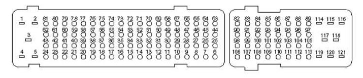
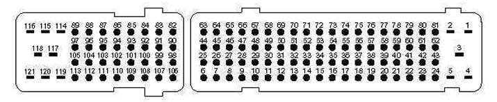
Reply part (from the harness side) control module connector
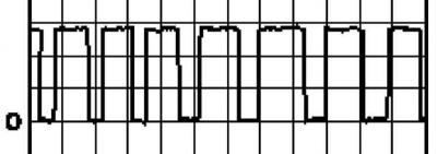
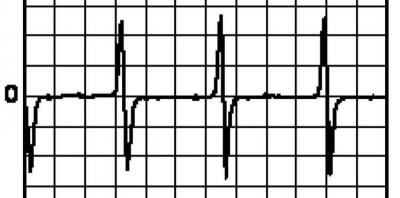
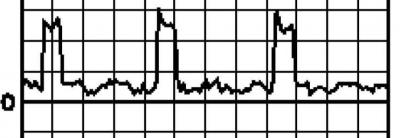
Waveform 1
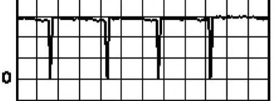
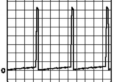
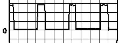
Waveform 2
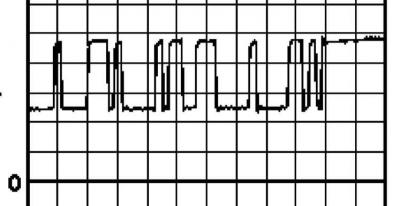
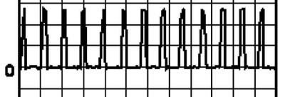
Waveform 3
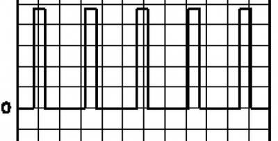
Waveform 4
Waveform 5
Waveform 6
Waveform 7
Waveform 8
Waveform 9
|
Conclusion |
Chain, Signal from/to/data exchange |
Meaning signal provided |
|
1 |
Weight |
Ignition on: 0V |
|
2 |
Weight |
Ignition on: 0V |
|
3 |
To engine management relay |
Ignition off: 0V |
|
3 |
To engine management relay |
Ignition on: 11-14V |
|
27 |
To tachometer |
idle speed: 5V/1ms per division (see illustration Waveform 1) |
|
27 |
From the control module e / motor fan of the cooling system |
idle speed: 5V/10ms per division (see illustration Waveform 1) |
|
28 |
From the control module e / motor fan of the cooling system |
Data not provided |
|
41 |
The module of management of the e/motor of the fan of the cooling system - K/V |
Data not provided |
|
66 |
The module of management of the e/motor of the fan of the cooling system - K/V |
Data not provided |
|
28 |
From the coolant temperature gauge |
Idle speed: No data given |
|
29 |
To digital fault display |
idle speed: 11-14V |
|
29 |
To digital fault display |
Ignition on: 11-14V |
|
30 |
Foot brake pedal position switch (BPP) |
Ignition on, pedal released: 0V |
|
30 |
To BPP switch |
Ignition on, pedal depressed: 11-14V |
|
65 |
To BPP switch |
Ignition on, pedal released: 11-14V |
|
65 |
To BPP switch |
Ignition on, pedal depressed: 0V |
|
31 |
transmission control module (TCM) - 2.0 |
Data not provided |
|
34 |
transmission control module (TCM) - 2.0 |
Data not provided |
|
67 |
transmission control module (TCM) - 2.0 |
Data not provided |
|
31 |
To clutch pedal position switch (CPP) |
Ignition on, pedal released: 11-14V |
|
31 |
To CPP switch |
Ignition on, pedal depressed: 0V |
|
33 |
Relay K/V |
Verification data not provided |
|
35 |
To engine immobilization control module |
Ignition off: 0V |
|
35 |
To engine immobilization control module |
Ignition on: 11-14V |
|
38 |
To accelerator pedal position sensor (APP) |
Ignition on, pedal released: 0.5V |
|
38 |
To APP sensor |
Ignition on, pedal depressed: 3.5V |
|
49 |
APP sensor |
Ignition on: 0V |
|
57 |
From APP sensor |
Ignition off: 0V |
|
57 |
From APP sensor |
Ignition on: 5V |
|
69 |
To APP sensor |
Ignition on, pedal released: 3.5V |
|
69 |
To APP sensor |
Ignition on, pedal depressed: 0.1V |
|
39 |
To ignition switch |
Ignition off: 0V |
|
39 |
To ignition switch |
Ignition on: 11-14V |
|
42 |
From the control lamp of failures (MIL) |
Ignition on, lamp on: 0V |
|
42 |
From the control lamp of failures (MIL) |
Ignition on, lamp off: 11-14V |
|
43 |
From the preheat indicator lamp |
Ignition on, lamp on: 0V |
|
43 |
From the preheat indicator lamp |
Ignition on, lamp off: 11-14V |
|
45 |
Tempostat master switch |
Verification data not provided |
|
63 |
Tempostat master switch |
Verification data not provided |
|
64 |
Tempostat master switch |
Verification data not provided |
|
58 |
Engine management relay - ground switching |
Ignition off: 11-14V |
|
58 |
Engine management relay - ground switching |
Ignition on: 0V |
|
60 |
To the control throttle valve EGR - 2.0 |
Ignition on: 11-14V |
|
60 |
Control throttle valve EGR - 2.0 |
idle speed: 5V/5ms per division (see illustration Waveform 2) |
|
68 |
To speed sensor (VSS) |
Ignition on: 0 or 11-14V |
|
68 |
To speed sensor (VSS) |
Ignition on - vehicle moving: 5V/10ms per division (see illustration Waveform 1) |
|
82 |
From the absolute pressure sensor in the pipeline (MAP) |
5V |
|
93 |
MAP sensor - ground |
Ignition on: 0V |
|
85 |
To MAP sensor |
idle speed: 0V |
|
85 |
To MAP sensor |
Idle speed - fast acceleration: 2.85V |
|
83 |
From air mass sensor (MAF) |
Ignition on: 5V |
|
88 |
To MAF sensor |
1.1V |
|
88 |
To MAF sensor |
idle speed: 1.1V |
|
88 |
To MAF sensor |
Idle speed - fast acceleration: 3.7V |
|
92 |
MAF sensor - ground |
Ignition on: 0V |
|
84 |
To MAF sensor - intake air temperature |
Ignition on, air temperature 20°C: 2.2V |
|
86 |
To engine oil temperature sensor |
Idle speed, engine warm: 2.47B |
|
86 |
To engine oil temperature sensor |
Idle speed, engine cold: 3.77V |
|
93 |
Engine oil temperature sensor - ground |
Ignition on: 0V |
|
87 |
From the preheat control module |
idle speed: 0.3V |
|
87 |
From the preheat control module |
Ignition on: 0.3V |
|
89 |
To coolant temperature sensor (ECT) |
Ignition on, fluid temperature 20°C: 3.7V |
|
89 |
To ECT sensor |
Idle speed, engine warm: 1.1V |
|
93 |
ECT sensor - ground |
Ignition on: 0V |
|
90 |
To crankshaft position sensor (CKP) |
idle speed: 3.8V ac |
|
90 |
To CKP sensor |
idle speed: 5V/5ms per division (see illustration Waveform 3) |
|
98 |
CKP sensor - ground |
Ignition on: 0V |
|
101 |
CKP sensor shield wire - earth |
Ignition on: 0V |
|
91 |
From the injection pump control module |
idle speed: 2V/5ms per division (see illustration Waveform 4) |
|
99 |
Injection pump control module - data exchange |
idle speed: 1.5—2.5V |
|
99 |
Injection pump control module - data exchange |
idle speed: 2V/10 µs per division (see illustration Waveform 5) |
|
99 |
Injection pump control module - data exchange |
Ignition on: 2.5V |
|
100 |
Injection pump control module - data exchange |
Ignition on: 2.5V |
|
100 |
Injection pump control module - data exchange |
idle speed: 2.5—3.5V |
|
100 |
Injection pump control module - data exchange |
idle speed: 0.5V/10 µs per division (see illustration Waveform 6) |
|
105 |
Injection pump control module - data exchange |
Ignition on: 0V |
|
105 |
Injection pump control module - data exchange |
idle speed: 0.1V/10ms per division (see illustration Waveform 7) |
|
94 |
From the preheat control module |
idle speed: 11-14V |
|
94 |
From the preheat control module |
Ignition on: 0V |
|
96 |
To the bleed valve-regulator of the turbocharger - 2.0 |
Engine running: 5V/10ms per division (see illustration Waveform 8) |
|
96 |
To the bleed valve-regulator of the turbocharger - 2.0 |
Ignition on: 11-14V |
|
97 |
From e/m valve EGR |
Ignition on: 11-14V |
|
97 |
From e/m valve EGR |
idle speed: 5V/1ms per division (see illustration Waveform 9) |
Visitor comments