
OpelBook.ru
Cars AvtoVAZ Cars Mitsubishi Cars BMW Cars Mercedes Cars Nissan Cars Toyota Cars Chevrolet
English Русский
Български
Беларускі
Український
Српски
Hrvatski
Română
Polski
Slovenský
Magyar
 |  Sitemap  |  Contacts  |    


Main Astra Corsa Insignia Kadett Omega Vectra Zafira Others Articles
Astra F (1991-1998, petrol) Astra G (1998-2004, petrol) Astra G (1998-2004) Astra H (2004-2009) Astra J (2009-2015, petrol)
  • Main
  • Astra
  • Astra G
  • Power unit
  • Injection system (diesel)
  • Removal and installation fuel injectors

Removal and installation fuel injectors (Opel Astra G)

            0

Contents: 1.7L SOHC Models ⬇ Models 1.7L DOHC ⬇ 2.0L models ⬇
Be especially careful! Do not place your hands or other body parts under the injector nozzles!


Do not allow dirt to enter the fuel system tract!


Remember that injectors are precision equipment and should be handled with extreme care!


1.7L SOHC Models


1. Disconnect the fuel return lines from the injectors.
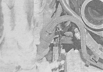
1. Disconnect the fuel return lines from the injectors.


2. Thoroughly wipe the union connectors connecting the fuel lines to the injectors, then loosen the union nuts. When disconnecting the tubes from the pump, hold the mating part of the connector with a second open-end wrench. After disconnecting the connectors, remove the fuel lines from the engine, immediately collect spilled fuel with a clean rag.
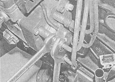
2. Thoroughly wipe the union connectors connecting the fuel lines to the injectors, then loosen the…


3. Wipe the surfaces around the injectors and remove the latter from the cylinder head.


Unscrew not only the injector body, but also its base, since otherwise there is a high risk of internal components falling out, and assembly will require a number of adjustments, which can only be performed in a car service workshop.


4. Remove the seals from the injector seating holes (flame retardant) washers, when assembling the washers must be replaced without fail. Try not to attempt to disassemble the injectors on your own.

5. Diagnostics of the injector condition requires the use of special equipment and should be entrusted to car service specialists.

6. Begin installation by placing the seals in the cylinder head (flame retardant) washers.
6. Begin installation by placing the seals in the cylinder head (flame retardant) washers.


7. Carefully screw in the injectors and tighten them to the required torque.

8. Finally, install the fuel lines and ensure that the union nuts are tightened to the required torque.

Models 1.7L DOHC


1. Remove the timing cover (see Chapter Engine).

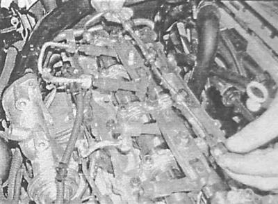
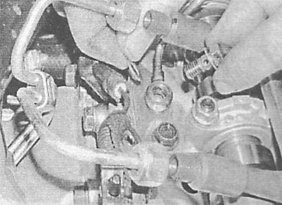
2. Remove the five mounting bolts and the inner fuel return line. Remove the copper sealing washers. New copper sealing washers are installed on both sides of the fuel return line nipple connectors to the injectors.
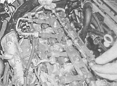


2. Remove the five mounting bolts and the inner fuel return line. Remove the copper sealing…


The washers of the connectors connecting the tubes to the timing case are also subject to replacement.
The washers of the connectors connecting the tubes to the timing case are also subject to…


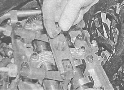
3. Loosen the mounting nuts and remove the injector mounting clamps.
3. Loosen the mounting nuts and remove the injector mounting clamps.


4. Remove the injectors from the cylinder head, the copper sealing washers must be replaced. Discard the rubber seals and copper washers. Try not to attempt to disassemble the injectors yourself.


5. Diagnostics of the injector condition requires the use of special equipment and should be entrusted to car service specialists.

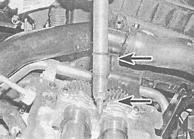
6. Begin assembly by cleaning the mating surfaces of the injectors and the cylinder head. Install new rubber and copper seals on each injector - make sure the copper washers are positioned correctly.
6. Begin assembly by cleaning the mating surfaces of the injectors and the cylinder head. Install…


7. Install the injectors into the cylinder head and secure them with mounting clamps. Tighten the clamp mounting nuts to the required torque.

8. Connect the fuel return line to the timing case and injectors. The tube is secured to the timing case using a larger diameter bolt (don't forget to replace the copper sealing washer), new copper sealing washers should be installed on the top of the injector and under each bolt. Tighten the bolts to the specified torque.

9. Install the timing case cover (see Chapter Engine).

10. Start the engine and check for signs of developing leaks.

2.0L models


To remove the injector nozzle from the cylinder head, you will need the KM-928-B puller with the KM-931 adapter mandrel. New adapter tube bolts will be required for installation.


1. Remove the upper section of the intake manifold (see above Models 1.7L DOHC, p.7).


2. Remove the camshaft and valve drive levers (see Chapter Engine).

3. Disconnect the return pipe from the injector adapter pipe.

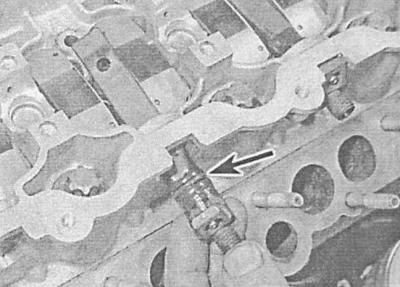
4. Loosen the mounting bolt, carefully separate the adapter tube from the top of the injector nozzle and remove it from the cylinder head.
4. Loosen the mounting bolt, carefully separate the adapter tube from the top of the injector…


5. Remove the sealing rings from the adapter tube and the upper part of the injector nozzle - the rings must be replaced without fail.
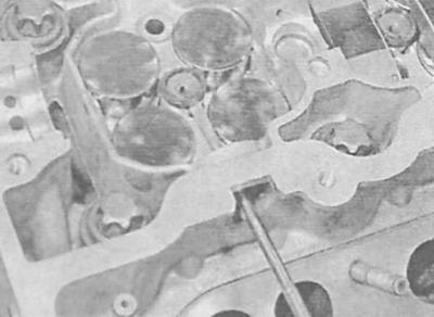
5. Remove the sealing rings from the adapter tube and the upper part of the injector nozzle - the…


6. Install the mandrel and puller on the top of the injector nozzle and evenly and carefully remove the nozzle from the top of the cylinder head. Remove and discard the sealing rings installed in the base of the nozzle - the rings must be replaced during assembly.

7. Place new sealing rings on the nozzle bases, then carefully insert the nozzles into the top of the cylinder head, ensuring that their guide pins are correctly aligned with the recesses in the head.
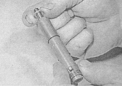
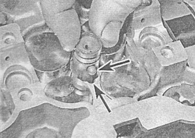

7. Place new sealing rings on the nozzle bases, then carefully insert the nozzles into the top of…


7. Place new sealing rings on the nozzle bases, then carefully insert the nozzles into the top of…


8. Make sure that the injector nozzle fits tightly in the cylinder head, place a new sealing ring on its upper part.

9. Place new sealing rings into the lugs on the adapter tubes. Install the adapter tubes in their proper places in the cylinder head, making sure they are positioned correctly on the top of the injector nozzles. Screw in new mounting bolts, tighten them until they stop by hand.
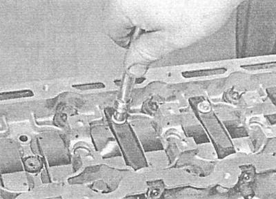
9. Place new sealing rings into the lugs on the adapter tubes. Install the adapter tubes in their…


10. Then tighten the key another full turn (360°).
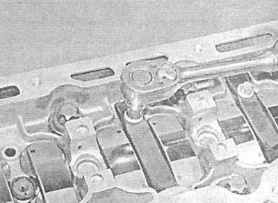


10. Then tighten the key another full turn (360°).


11. Connect the return line to the adapter tubes and install the upper part of the inlet pipe (see Removal and installation the intake manifold).

12. Install the camshaft and valve drive levers in place (see Chapter Engine).


This article is available at russian, bulgarian, belarusian, ukrainian, serbian, croatian, romanian, polish, slovak, hungarian
Checking the article: Pavlovsky Nikolay

Share information:

Previous articles
Opel Astra G: Injection system (diesel)
Next articles

Removal and installation of fuel injection pump
Signals and voltages at the control module terminals
Removal and installation of electrical components of the power supply system
Checking and adjusting fuel injection timing settings
Checking and adjusting maximum engine speed
Diesel engine injection and turbocharging systems
Removal and installation a turbocharger
Removal and installation the intermediate cooler (intercooler)
Removal and installation the intake manifold
Removal and installation the exhaust manifold


See similar ones from other Opel car manuals:
▶ Replacing fuel injectors (one or all) (Z10XE, Z10XEP,… Opel Corsa C (2000-2006, petrol)
▶ Diagnostics and cleaning of fuel injectors Opel Insignia A (2008-2017)
▶ Fuel injectors — checking, removal and installation Opel Omega B2 (1999-2003)
▶ Fuel injectors (except Multec system) — removal and… Opel Vectra A (1988-1995, petrol)
▶ Removal and installation of fuel rail and injectors Opel Vivaro A (2001-2014)
Link to this page in different formats

Visitor comments


No comments yet


How much will 26 + 37 =


Astra J (2009-2015, petrol) 
  • General information
  • Vehicle device
  • User manual
  • Faults en route
  • Maintenance
  • Power unit
  • Engine repair
  • Cooling and lubrication system
  • Engine power system
  • Exhaust system
  • Transmission
  • Clutch
  • Car gearbox
  • Drive shafts
  • Chassis
  • Front suspension
  • Rear suspension
  • Steering
  • Brake system
  • Wheels and tires
  • Body
  • Exterior
  • Interior
  • Doors and windows
  • Body Care
  • Heating and air conditioning
  • Security systems
  • Electrical equipment
  • Equipment and devices
  • Lighting and signaling
  • Power devices
  • Electrical circuits
Astra H (2004-2009) 
  • General information
  • Introduction to the guide
  • Troubleshooting
  • User manual
  • Maintenance
  • Power unit
  • Engine repair
  • Cooling and heating
  • Power and exhaust system
  • Ignition system
  • Launch and charge system
  • Transmission
  • Mechanical gearbox
  • Automatic gearbox
  • Drive shafts
  • Chassis
  • Brake system
  • Car suspension
  • Steering
  • Body
  • Interior
  • Exterior
  • Electrical equipment
  • Equipment and devices
  • Electrical circuits
Astra G (1998-2004) 
  • General information
  • Introduction to manual
  • User manual
  • Maintenance
  • Power unit
  • SOHC gasoline engines
  • DOHC gasoline engines
  • Diesel engines 1.7 and 2.0
  • Engine repair
  • Cooling system
  • Supply system
  • Injection system (gasoline)
  • Injection system (diesel)
  • Exhaust system
  • Charge and launch system
  • Ignition system (gasoline)
  • Preheat system (diesel)
  • Transmission
  • Manual gearbox
  • Automatic gearbox
  • Clutch
  • Drive shafts
  • Chassis
  • Brake system
  • Wheel suspension
  • Steering
  • Body
  • Exterior
  • Interior
  • Doors and windows
  • Ventilation and heating
  • Electrical equipment
  • Equipment and devices
  • Electrical circuits
Astra G (1998-2004, petrol) 
  • General information
  • User manual
  • Car care
  • Maintenance
  • Power unit
  • Single shaft engines
  • Twin shaft engines
  • Engine repair
  • Cooling and heating
  • Fuel and exhaust systems
  • Starting and charging system
  • Ignition system
  • Transmission
  • Clutch
  • Mechanical gearbox
  • Automatic gearbox
  • Drive shafts
  • Chassis
  • Brake system
  • Car suspension
  • Steering
  • Body
  • Interior
  • Exterior
  • Electrical equipment
  • Equipment and devices
  • Wiring diagrams Opel Astra
  • Wiring diagrams Opel Zafira
Astra F (1991-1998, petrol) 
  • General information
  • Maintenance
  • Power unit
  • Engine in car
  • Engine removed
  • Cooling system
  • Heating and ventilation
  • Fuel supply (carburetor)
  • Fuel supply (injector)
  • Emission control
  • Ignition system
  • Transmission
  • Clutch
  • Mechanical gearbox
  • Automatic gearbox
  • Drive shafts
  • Chassis
  • Brake system
  • Car suspension
  • Steering
  • Body
  • Exterior
  • Interior
  • Electrical equipment
  • Equipment and devices
  • Electrical circuits
OpelBook.ru © 2017–2026 · Mobile version · · Sitemap: EN BG BY UA RS HR RO PL SK HU · Feedback · Site search
Astra F, petrol · Astra G, petrol · Astra G · Astra H · Astra J, petrol · Corsa B · Corsa C, petrol · Corsa C · Insignia A · Kadett D · Kadett E · Omega A · Omega B · Omega B2 · Vectra A, petrol · Vectra A · Vectra B, petrol · Vectra B · Vectra C · Zafira A, petrol · Frontera A, petrol · Frontera B · Ascona C · Vivaro A ·
We want your visit to be comfortable 🤝! We use cookies 🍪 to make that happen.