
Models 1.7L SOHC
Air mass sensor (MAF)
intake air temperature sensor (IAT) built into the MAF sensor.
1. Turn off the ignition and disconnect the wiring from the sensor.
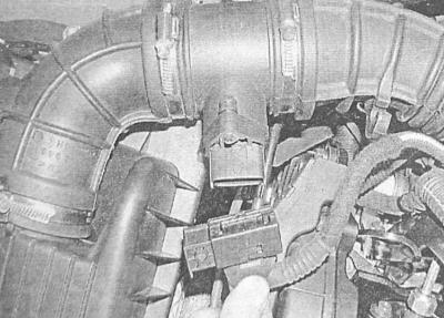
2. Release the clamps, disconnect the electrical wiring from the sensor and remove the sensor from the vehicle.
3. Installation is carried out in the reverse order. Make sure that the sensor and air ducts are securely fixed.
Accelerator pedal position sensor
1. At the time of writing this manual, the pedal assembly was produced as a monolithic assembly and, in the event of a malfunction, was subject to replacement as an assembly.
2. In the passenger compartment, unscrew the fasteners and, in order to provide access to the pedal assembly, remove the left lower section of the instrument panel trim (see chapter Body).
3. Give fixing nuts and remove assembly of an accelerator pedal from a bulkhead of an impellent compartment.
4. Release the clamp and disconnect the wiring from the sensor.
5. Installation is carried out in the reverse order. Make sure that the electrical wiring is connected correctly and that the fasteners are tightened with the required force.
6. Do not forget to install the finishing section of the instrument panel.
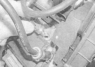
Crankshaft position sensor (CKP)
1. The sensor is installed in the front of the cylinder block, - disconnect the electrical wiring, try to remember the order of its laying.
2. Turn out a fixing bolt and remove the gauge.
3. Installation is carried out in the reverse order. Make sure the fasteners are tightened to the correct torque.
Coolant temperature sensor (ECT)
1. The coolant temperature sensor is installed in the thermostat housing on the right side of the cylinder head, - disconnect the electrical wiring.
2. Empty the cooling system (see chapter Current service), prepare to collect spilled coolant.
3. Unscrew the sensor from the thermostat housing, - first open the cover of the expansion tank to relieve excess pressure in the path, then put the cover back and tighten it tightly. Having unscrewed the sensor, immediately plug the hole for its installation with a rubber plug in order to minimize the loss of coolant.
4. Lubricate the threaded part of the sensor with sealant before installation. Screw the sensor into the mounting socket and tighten it with the required force.
5. Connect the wiring to the sensor.
6. Fill the cooling system (see chapter Current service).
Boost pressure sensor
1. The boost pressure sensor is installed on the right in the intake manifold, - disconnect the electrical wiring.
2. Remove the fixing screw and remove the sensor from the pipeline.
3. Installation is carried out in the reverse order. Make sure the fasteners are tightened to the correct torque.
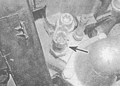
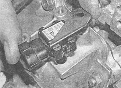
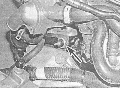
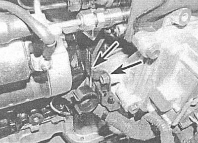
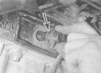
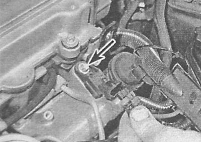
Emergency oil pressure sensor
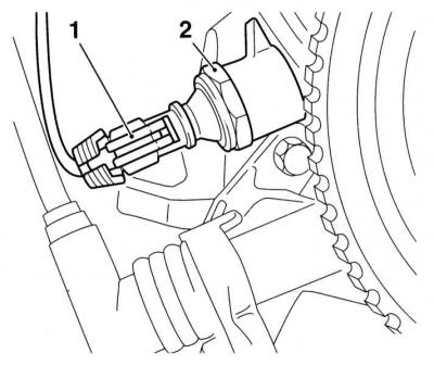
1 - electrical wiring connector
2 - emergency oil pressure sensor
The sensor is screwed into the back of the oil pump housing. The signals generated by the sensor are used by the ECM to control the functioning of the indicator lamp located on the instrument panel.
1. Set the parking brake, jack up the front of the car and place it on supports, if equipped, remove the crankcase protection.
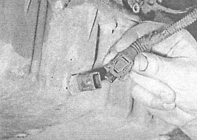
2. Disconnect the wiring from the sensor.
3. Unscrew the sensor, - get ready to collect the spilled oil, immediately plug the hole for installing the sensor with a suitable plug.
4. Installation is carried out in the reverse order. With the appropriate configuration, do not forget to replace the sealing element, make sure that the sensor is tightened with the required force.
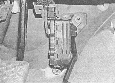
Electronic engine control module (ECM)
Before removing the ECM, decode it in a car service workshop.
1. The ECM is installed under the left front wheel arch locker. Set the parking brake, jack up the front of the car and place it on jack stands, remove the wheel.
2. Turn out fixing screws and remove a locker.
3. Disconnect the electrical wiring and remove the ECM from the support bracket.
4. Installation is carried out in the reverse order. Make sure that the wiring is connected correctly and securely fixed.
Electronic injection pump control module
The injection pump control module is built into the pump assembly. The compilers of this Guide do not recommend attempting to dismantle the module.
Fuel temperature sensor
The sensor is built into the pump assembly. The compilers of this Guide do not recommend attempting to dismantle the sensor.
Injection pump shaft position sensor
The sensor is built into the pump assembly. The compilers of this Guide do not recommend attempting to dismantle the sensor.
Injection start sensor
The sensor is built into the pump assembly. The compilers of this Guide do not recommend attempting to dismantle the sensor.
Shut-off solenoid valve
The sensor is built into the pump assembly. The compilers of this Guide do not recommend attempting to dismantle the sensor.
Models 1.7L DOHC
Air mass sensor (MAF)
intake air temperature sensor (IAT) built into the MAF sensor.
See above Models 1.7L SOHC, corresponding subsection.
Accelerator pedal position sensor
See above Models 1.7L SOHC, corresponding subsection.
Crankshaft position sensor (CKP)
1. Engage the parking brake, jack up the vehicle and place it on jack stands, remove the crankcase if equipped.
2. The sensor is installed at the rear of the cylinder block, under the starter. Climb under the car and disconnect the electrical wiring from the sensor - try to remember the order of its laying.
3. Turn out a fixing bolt and remove the gauge, - a sealing ring is subject to replacement without fail.
4. Installation is carried out in the reverse order. Do not forget to replace the sealing ring, make sure that the fasteners are tightened with the required force.
Coolant temperature sensor (ECT)
See above Models 1.7L SOHC, corresponding subsection.
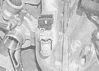
Boost pressure sensor
1. Remove the air cleaner air duct installed in the rear of the engine compartment (see Removal and installation of components of an inlet air path).
2. Remove the EGR valve from the intake manifold (see Systems of release and decrease in toxicity of the fulfilled gases).
3. Disconnect the wiring from the sensor attached to the right on the inlet pipeline.
4. Turn out fixing bolts and remove the gauge.
5. Installation is carried out in the reverse order. Make sure the fasteners are tightened to the correct torque.
Emergency oil pressure sensor
1. The signals generated by the sensor are used by the ECM to control the functioning of the indicator lamp located on the instrument panel.
2. Remove the battery with support bracket (see chapter Engine electrical equipment).
3. The gauge is located at the left on the block of cylinders, disconnect from it an electroconducting.
4. Unscrew the sensor from the block - get ready to collect the spilled oil.
5. Lightly lubricate the threaded part of the sensor with sealant. Screw in the sensor and tighten it to the required torque.
6. Connect the wiring, then replace the battery with the support bracket.
7. Start the engine and check it for signs of leak development.
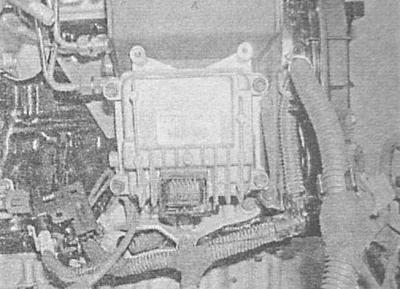
Electronic engine control module (ECM)
Before removing the ECM, decode it in a car service workshop.
1. The ECM is placed on top of the engine, above the EGR valve.
2. Disconnect the negative cable from the battery.
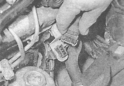
3. Release spring clips and disconnect two contact sockets of electroconducting ECM, - try not to damage sockets.
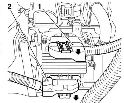
4. Turn out fixing bolts/nuts and remove ECM.
5. Installation is carried out in the reverse order. Make sure that the wiring is connected correctly and securely fixed. The connectors differ from each other in design, a harness is connected to the rear socket, coming from the left side of the engine compartment.
Electronic injection pump control module
The injection pump control module is located at the rear of the pump assembly.
1. Set the parking brake, jack up the front of the car and place it on supports, if equipped, remove the crankcase protection.
2. Climb under the vehicle and disconnect the electrical wiring from the control module.
3. Turn out fixing bolts and remove the control module.
4. Installation is carried out in the reverse order.
Turbocharging system safety solenoid valve
1. Set the parking brake, jack up the front of the car and place it on supports, if equipped, remove the crankcase protection.
2. Acting in accordance with the instructions above (see Electronic injection pump control module), remove the injection pump control module.
3. Disconnect the vacuum tube and wiring from the valve.
4. Turn out two fixing bolts and remove the electromagnetic valve.
5. Installation is carried out in the reverse order. Track reliability of a tightening of fixing bolts. Pay attention to the difference in the thickness of the vacuum tubes - the smaller one is connected to the inlet fitting.
Atmospheric pressure sensor (BARO)
The sensor is installed at the rear of the cylinder block, between the injection pump and the starter.
1. Set the parking brake, jack up the front of the car and place it on supports, if equipped, remove the crankcase protection.
2. Disconnect the wiring from the sensor.
3. Lift the sensor up and out of the support bracket.
4. Installation is carried out in the reverse order.
Fuel temperature sensor
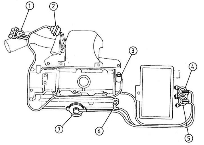
Injection pump components (1.7L DOHC models)
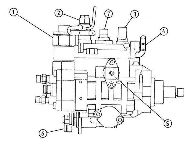
1 - Drain valve
2 - Fuel return line
3 - Fuel temperature sensor
4 - Fuel supply line
5 - Programmable memory block
6 — the Solenoid valve of management of the moment of injection (PROM)
7 - Shaft position sensor injection pump
The sensor is installed at the top right of the injection pump assembly (see illustration Injection pump components (1.7L DOHC models)).
1. Disconnect the electrical wiring and unscrew the sensor from the pump assembly.
2. After replacing the sealing element, screw the sensor into the injection pump and tighten the nut securely.
3. Restore the original wiring connection.
Injection pump shaft position sensor
The sensor is placed on the side of the injection pump assembly (see illustration Injection pump components (1.7L DOHC models)) and individually, spare parts are not supplied to the market, if necessary, seek advice from the specialists of the Opel branded service station.
Injection start sensor
The sensor is located under the injection pump, closer to the flywheel / drive disk and is not supplied individually to the spare parts market, if necessary, contact Opel branded service specialists for advice.
Solenoid shut-off valve
The valve is installed in the upper part of the high-pressure fuel pump, closer to the flywheel / drive disk and is not supplied individually to the spare parts market, if necessary, contact the specialists of the Opel branded service station for advice.
2.0 liter models
Air mass sensor (MAF)
intake air temperature sensor (IAT) built into the MAF sensor.
See above Models 1.7L SOHC, corresponding subsection.
Accelerator pedal position sensor
See above Models 1.7L SOHC, corresponding subsection.
Crankshaft position sensor (CKP)
1. Turn out fixing screws and remove a plastic protective casing from the top part of a head of cylinders a plastic cover from above a head of cylinders.
2. In order to ensure adequate access to the sensor, cock the parking brake, jack up the front of the car and place it on props, if equipped, remove the crankcase protection.
3. Walk along the wiring harness from the sensor to the electrical wiring connector. Release the connector from the support bracket and disconnect it.
4. Wipe the surface of the engine around the sensor, then remove the mounting bolt and remove the sensor from the front of the cylinder block, remove the sealing ring.
5. Installation is carried out in the reverse order. Do not forget to replace the sealing ring, make sure that the mounting bolt is tightened with the required force.
Coolant temperature sensor (ECT)
The sensor is screwed into the front of the cylinder head from the right, refer to the instructions for removing and installing the sensor. Check of serviceability of functioning, removal and installation of electric components of a chain of management of the engine cooling system.
Boost pressure sensor
1. Turn out fixing screws and remove a plastic protective casing of the engine.
2. Turn out screws of fastening of a routing trench of an electroconducting to the top part of the inlet pipeline and disconnect from the gauge electroconducting.
3. Turn out a fixing bolt and remove the gauge from the top part of the inlet pipeline, - pay attention to the sealing ring planted on a shaft.
4. Installation is carried out in the reverse order. Do not forget to replace the sealing ring, make sure that the mounting bolt is tightened with the required force.
Oil temperature sensor
1. Set the parking brake, jack up the front of the car and place it on supports, if equipped, remove the crankcase protection.
2. Drain the engine oil (see chapter Current service), - at the end of the procedure, do not forget to screw in place the drain plug of the pan with a new sealing washer and tighten it with the required force.
3. Disconnect the electrical wiring and unscrew the sensor from the front of the crankcase.
4. Installation is carried out in the reverse order.
5. Finally, fill the engine with fresh oil (see chapter Current service).
Electronic engine control module (ECM)
Before removing the ECM, decode it in a car service workshop.
See above Models 1.7L SOHC, Emergency oil pressure sensor.
Electronic injection pump control module
The injection pump control module is built into the pump assembly. The compilers of this Guide do not recommend attempting to dismantle the module.
Intake manifold switching solenoid valve
Vacuum Line Routing Diagram on 2.0L High Pressure Turbo Models
1 - Solenoid valve for boost pressure control
2 - Actuator boost pressure control
3 - Vacuum pump
4 - EGR valve
5 - Electromagnet for controlling the operation of the intake manifold switching valve
6 — the Valve of switching of the inlet pipeline
7 - EGR valve
The engine has two valves: EGR valve (EGR) and intake manifold changeover valve. The latter is installed closer to the front of the car (see illustration Vacuum Line Routing Diagram on 2.0L High Pressure Turbo Models).
1. Disconnect the electrical wiring and vacuum hoses from the valve, remove the mounting screws and remove the valve from the support bracket.
2. Installation is carried out in the reverse order.
Solenoid relief valve for turbocharging system
The solenoid valve is installed in the right rear corner of the engine compartment.
1. In order to gain access to the valve to gain access to the valve, remove the intake duct (complete with MAF sensor), leading from the air cleaner to the turbocharger.
2. Disconnect from the valve electroconducting and vacuum hoses, turn out fixing screws and remove the valve from a basic arm.
3. Installation is carried out in the reverse order.
Visitor comments