


Contents: Front door trim ⬇ Rear door trim ⬇ Tailgate ⬇ Rear side trim panel (coupe models) ⬇ Rear side trim panel (hatchback…⬇ C-pillar trim panels (coupe models) ⬇ Lower sections of instrument panel…⬇ Other panels ⬇
Before you begin any work on the front seats, read the warning at the beginning Removal and installation front seats.
Installation diagram of electrical components located on the rear door interior trim panel (zafira models)
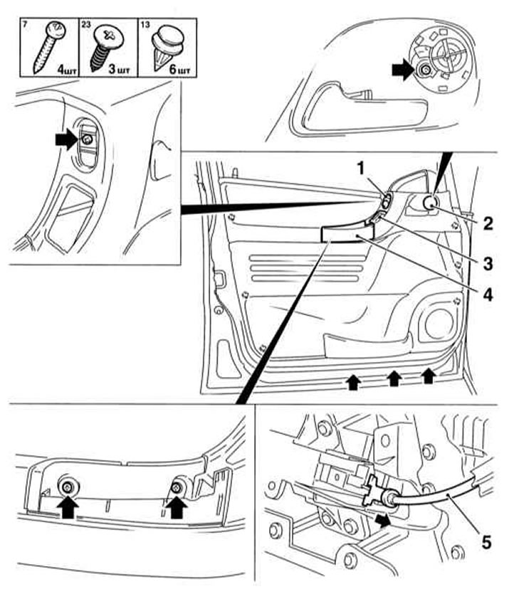
1 — Rear view mirror electric drive control switch
2 - High frequency loudspeaker
3 — Switch for controlling the operation of the electric window lifter
4 - Handle
5 — Door handle cable
Front door trim
1. Disconnect the negative battery cable. Wait at least one minute before proceeding with the upcoming work, during which time the SRS independent power supply capacitor should discharge.
2. On models with electrically adjustable outside mirrors rear view, carefully pry it up with a screwdriver and release it from the cover, remove the switch that controls the operation of the electric drive, - disconnect the electrical wiring from the switch, on models with electric windows, do the same procedure with the corresponding switch (see illustration Installation diagram of electrical components located on the rear door interior trim panel (zafira models)).
Text was copied from the portal [OPELBOOK]
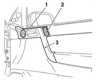
3. On models with manual window lifts remove the retaining clip and remove the window lift handle, being careful not to damage the trim panel. Remove the protective washer-cover from the panel.
4. Remove the protective cover from the door mirror adjustment handle, then remove the triangular decorative cover. Disconnect the wiring from the tweeter - if this speaker is installed in the trim panel, release it from there and disconnect the wiring (see illustration Installation diagram of electrical components located on the rear door interior trim panel (zafira models)).
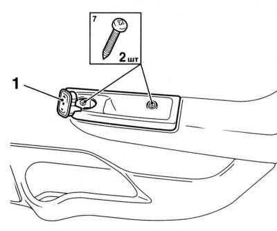
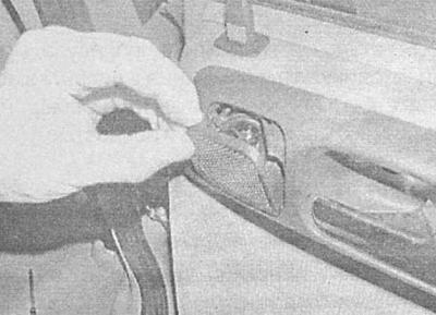
5. On astra models carefully remove the inner door handle cover (see illustration Installation diagram of electrical components located on the rear door interior trim panel (zafira models)) and remove the door handle.

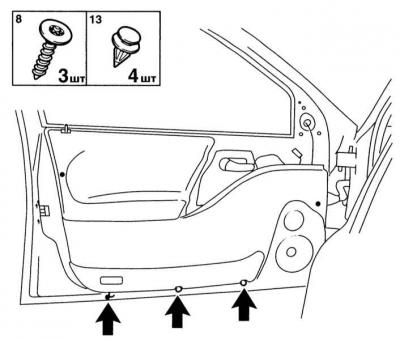
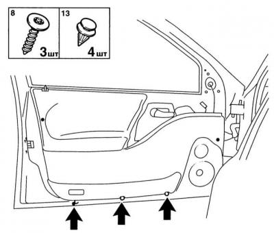
6. Remove the mounting screws in the lower section of the trim - on some models the screws are located under a cover that can be removed by removing the plug and screw.
7. Now you need to release the plastic fasteners of the interior trim panel from the door frame - use a flat-blade screwdriver, or better yet, a special fork-shaped device to avoid damaging the fasteners. The fasteners are located along the entire perimeter of the trim panel. To avoid damaging the paintwork, place cardboard under the edge of the panel.
8. After releasing the clips, disconnect the drive cable from the inside door handle. Separate the top edge of the panel from the door and remove the latter from the door frame.
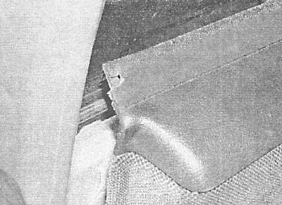
9. The glued insulating plastic membrane can be peeled off the door if necessary - act extremely carefully, try not to tear the membrane.
10. Installation is carried out in the reverse order. Replace broken plastic fasteners. If the membrane was removed, make sure it is securely glued in place.
Rear door trim
1. Disconnect the negative battery cable. Wait at least one minute before proceeding with the upcoming work, during which time the SRS independent power supply capacitor should discharge.
2. On models with electric windows carefully pry up the electric drive control switch with a screwdriver and release it from the cover - disconnect the electrical wiring from the switch.
On some models, the switch is secured with screws.
3. On models with manual window lifts remove the retaining clip and remove the window handle, being careful not to damage the trim panel.
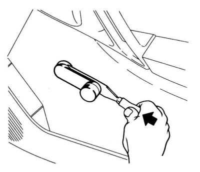
4. Remove the protective washer-cover from the panel.
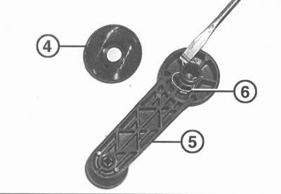
4 - Protective washer-cover
5 — Window lifter handle
6 - Fixing bracket
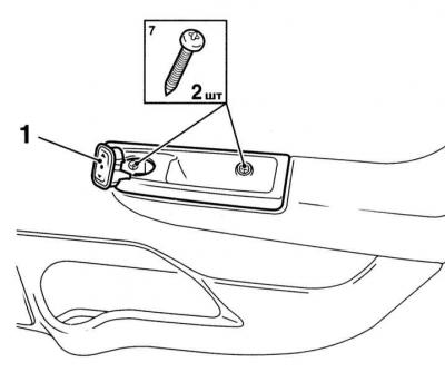
5. If necessary, remove the plastic cover, unscrew the mounting screws and remove the pocket from the trim panel.
6. Remove the ashtray, if necessary, release and remove the tweeter grille.
7. Remove the screws securing the lower section of the trim panel to the door frame.
8. Using a slotted screwdriver, or better yet, a special fork-type grip, pry up the panel and release the plastic fasteners located around its perimeter.
9. Release the clips, disconnect the drive cable from the inside door handle and the electrical wiring from the tweeter. Remove the trim panel.
10. If necessary, remove the plastic insulating membrane, having first removed the drive cable and rod - try to damage the membrane.
11. Installation is carried out in the reverse order. Do not forget to replace the fasteners damaged during removal. Ensure that the insulating membrane is securely fixed.
Tailgate
Schematic diagram of the arrangement of fastening elements of the interior trim panels of the rear door (hatchback models)
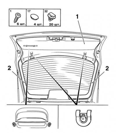
1 - Lower section of trim panel
2 - Upper section of trim panel
Schematic diagram of the arrangement of fastening elements of the interior trim panels of the rear door (models Universal)
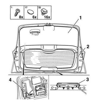
1 - Lower section of trim panel
2 - Upper section of trim panel
3 - High level brake light
4 — High-level brake light wiring connector
Schematic diagram of the arrangement of fastening elements of the interior trim panels of the rear door (zafira models)
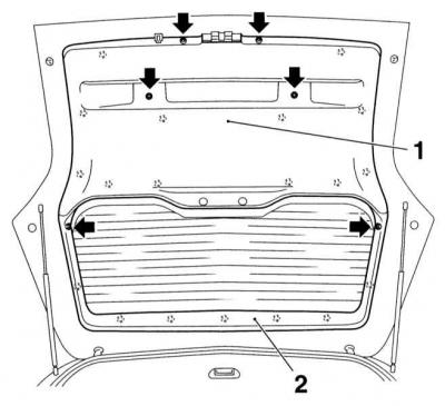
1 - Lower section of trim panel
2 - Upper section of trim panel
1. Open the door, remove the plastic plugs, unscrew the mounting screws and remove the upper and lower sections of the interior trim panel - note that the lower section has tabs that engage with the grooves in the upper section.
2. Loosen the fastener and remove the high level brake light.
3. Installation is carried out in reverse order.
Rear side trim panel (coupe models)
1. Remove the rear seat back (see Removal and installation rear seats).
2. Using a wide slotted screwdriver, release the clips and separate the panel from the body element. Be careful - try not to break the clips.
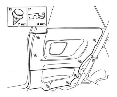
3. Installation is carried out in reverse order.
Rear side trim panel (hatchback models)
1. Open the rear door and tailgate, remove the rubber seal of the body opening near the side trim panel and the decorative trim of the sofa, remove the rear shelf.
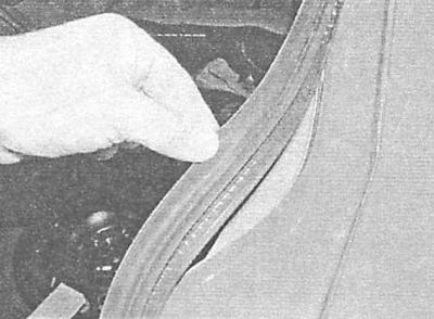
2. Remove the inner side trim from the corresponding side.
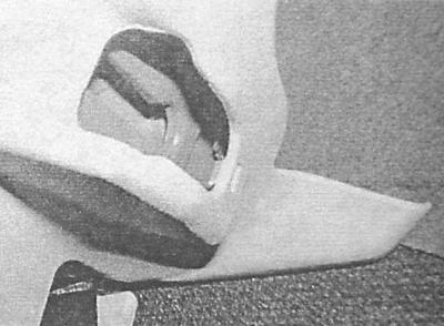
3. Remove the rear seat cushion (see Removal and installation rear seats), then fold the rear seatback forward.
4. Remove the mounting screws and remove the plastic cover from the rear seat cushion.
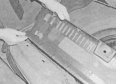
5. Release the plastic clips.
.
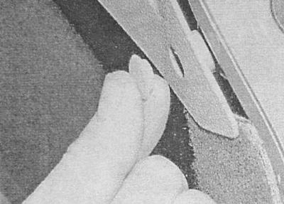
6. Remove the screws securing the upper section of the side trim to the body.
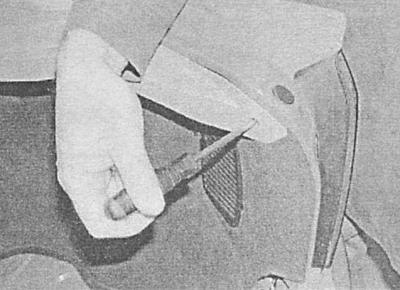
7. Remove the bolt securing the lower seat belt anchor bracket to the floor panel.
8. Release the fasteners and remove the upper cover, - release the seat belt from the groove in the cover.
A — Releasing the rear side trim panel fastening clips
B - Removing the lower section of the rear side trim panel
A.
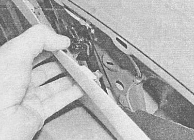
B.
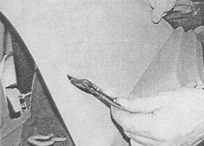
9. Remove the rubber bumper from the rear seat back.
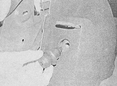
10. Release the clamps.
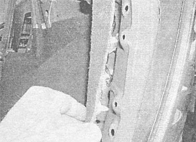
11. Remove the lower section of the side trim.
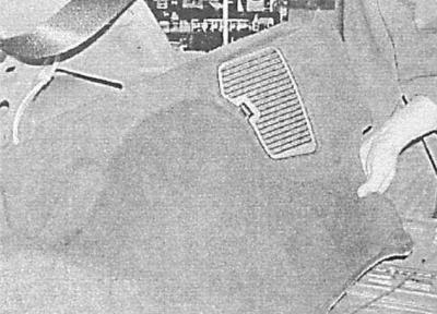
12. Installation is carried out in the reverse order. When seating the seal in the body opening, use a mallet.
C-pillar trim panels (coupe models)
1. Remove the rear side trim panel (see above).
2. Remove the mounting screws.
3. Using a wide slotted screwdriver, carefully release the clamps securing the panel to the rack - try not to break the clamps.
4. Installation is carried out in reverse order.
Lower sections of instrument panel trim
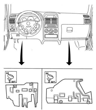
1. The lower sections of the instrument panel trim are attached to the driver's and front passenger's feet. First, remove the screws that attach the sections to the side of the heater.
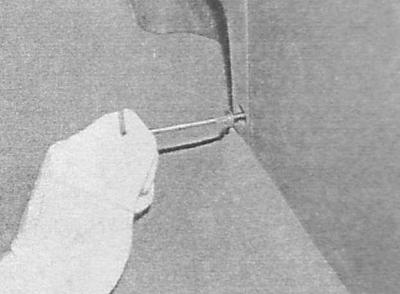
2. Remove the outer screws and remove the lower trim sections from the instrument panel.
A — Unscrewing the outer screws securing the lower section of the instrument panel trim
B — Installation diagram of the lower sections of the instrument panel trim
A.
B.
3. Installation is carried out in reverse order.
Other panels
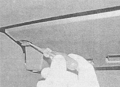
Most small decorative trims are attached with plastic clips, commonly called "bugs". When released, such clips easily break. In order to minimize losses, try to use a special fork-shaped grip to release the clips, which should be inserted directly under the clip flange, and not under the trim panel.
Visitor comments