


Contents: Footwell trim panels ⬇ Driver's side lower trim panel ⬇ Steering column covers ⬇ Lower instrument panel trim panel ⬇ Upper instrument panel trim panel ⬇ Light switch panel ⬇ Radio panel ⬇ Glove compartment assembly ⬇
Footwell trim panels
Removal
1. The lower trim panels of the passenger and driver's footwells are attached with plastic clips with screw-type fasteners.
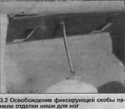
2. To remove the panel, use a screwdriver to turn the heads of the brackets 90° (see illustration), then remove the panel.
Installation
3. Install in reverse order.
Driver's side lower trim panel
Removal
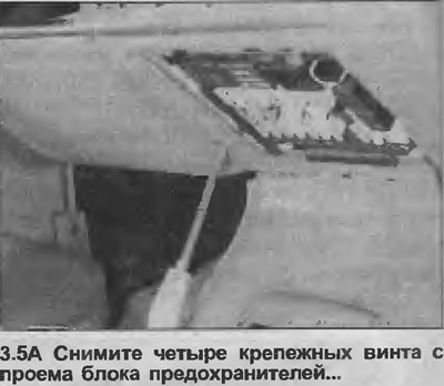
4. Open the flap covering the fuse box to expose the four lower instrument panel mounting screws.
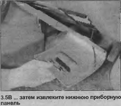
5. Remove the four screws, then lower the panel and pull it toward the driver's door to release the two retaining clips. Remove the panel (see illustrations).
Installation
6. Installation is carried out in reverse order.
Steering column covers
Removal
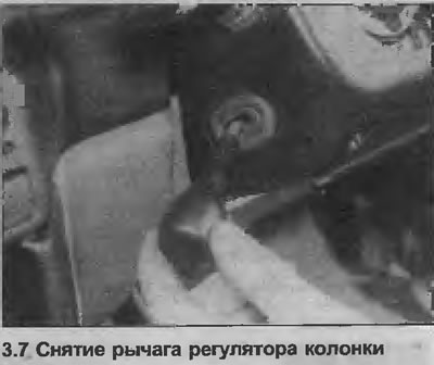
7. On models with tilt steering column, move the steering column to the fully raised position, then loosen the adjuster lever (see illustration).
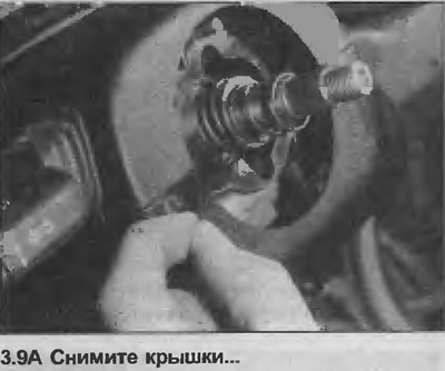
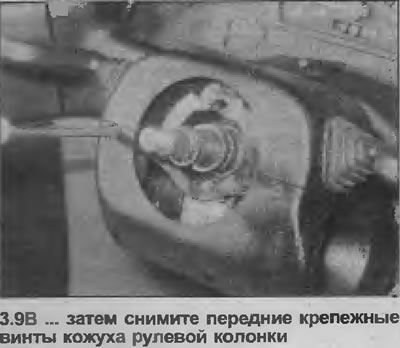
8. Turn the steering wheel as necessary to open one of the front steering column shroud screw covers.
9. Remove the cover and remove the screw securing the casing, then turn the left wheel to remove the remaining cover and screw that will be removed (see illustrations).
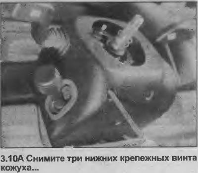
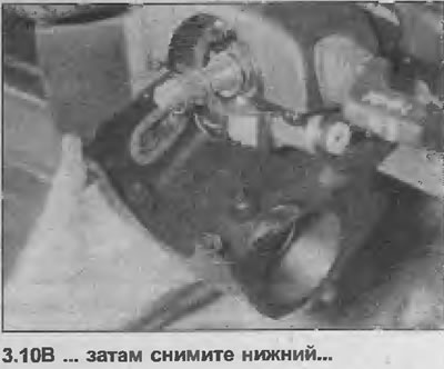
10. Remove the three mounting screws from the back of the speaker housing, then remove the lower and upper speaker housings (see illustrations).
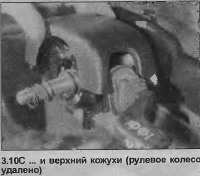
Installation
11. Installation is carried out in the reverse order, but make sure that the protective covers fit into the slots in the upper casing.
Lower instrument panel trim panel
Removal
12. Remove the steering column covers as described earlier in this Chapter.
13. The panel is secured with brackets at both ends, which are removed by pulling on the ends of the panel (see illustration). This is a tricky action, to pull out both ends, the panel should be slightly bent in the center. Be very careful, as the panel can easily be broken.

Installation
14. Installation is carried out in reverse order.
Upper instrument panel trim panel
Removal
15. Remove the lower instrument panel trim panel as described earlier in this Chapter.
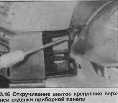
16. Remove the two lower trim panel mounting screws, one at each end, remembering that the left-hand threaded screw also secures the heater control panel (see illustration).
Original article on the web portal (www.OpelBook.ru)
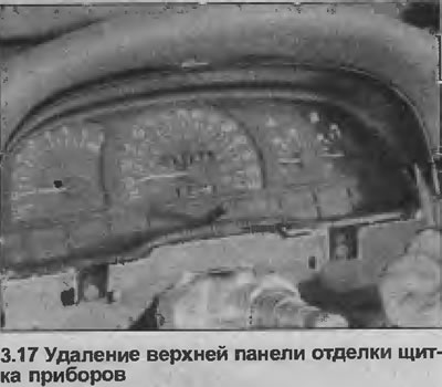
17. Remove the trim panel from the instrument panel (see illustration).
Installation
18. Installation is carried out in reverse order.
Light switch panel
Removal
19. Remove the upper and lower instrument panel trim panels as described earlier in this Chapter.
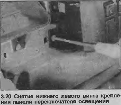
20. Remove the remaining screw from the left side of the light switch panel (see illustration)
21. Remove the light switch panel from the instrument cluster to remove the retaining clips on the right side.
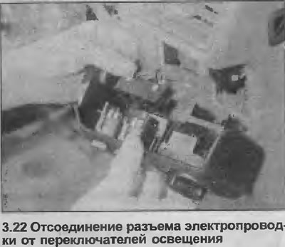
22. Make sure the negative battery cable is disconnected, then disconnect the wiring connectors from the switches and remove the switch panel (see illustration).
Installation
23. Installation is carried out in reverse order
Radio panel
Removal
24. Remove the radio as described in Section 12.
25. Remove the lower and upper instrument panel trim panels as described earlier in this Chapter.
26. Remove the lower mounting screw from the right side of the heater control panel
27. Remove the clock or trip computer from the panel, depending on the model, as described in Section 12, if necessary.
28. Remove the two screws securing the heater control panel from the clock/trip computer opening.
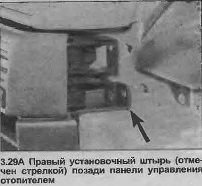
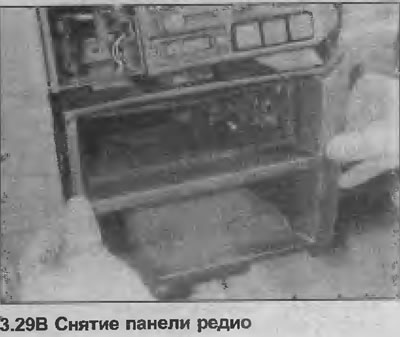
29. Gently push the heater control panel forward, within the length of the wires, then pull it out of the panel. This is a tricky step, as the radio panel mounting pins are behind the heater control panel mounting pins (see illustrations). Be careful not to deform the heater control cables.
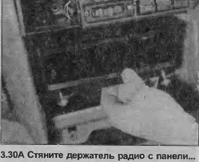
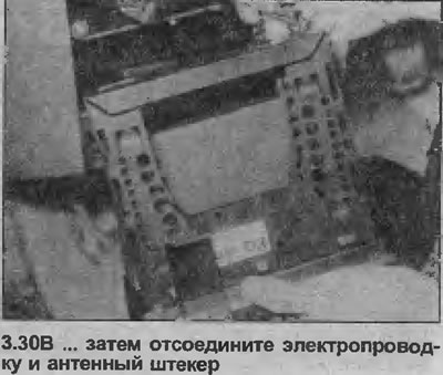
30. With the panel removed, the radio bracket can be removed if required by unscrewing the two mounting screws, then sliding the bracket forward to disconnect the wiring and antenna connector (see illustrations).
Installation
31. Installation is carried out in the reverse order, taking care not to damage the heater control components.
Glove compartment assembly
Warning: If an air bag is installed, read the warning in Section 12, before you start working.
Removal
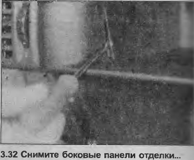
32. Using a screwdriver, carefully remove the side trim panels from the passenger luggage rack (see illustration).
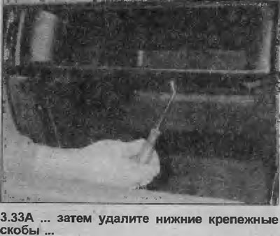
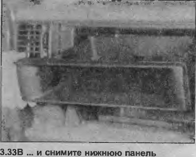
33. Open the glove compartment, then use a screwdriver to remove the two lower mounting brackets at the rear of the shelf and remove it (see illustrations).
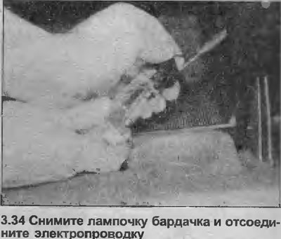
34. Where applicable, remove the glove compartment light bulb and disconnect the wiring (see illustration).
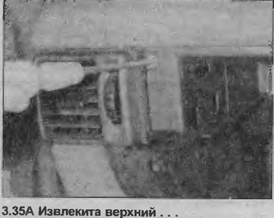
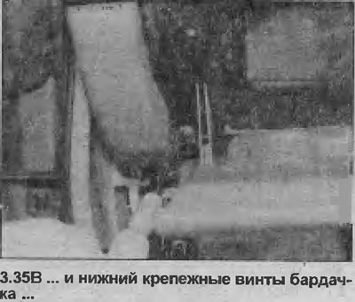
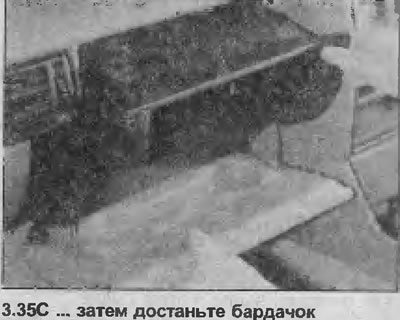
35. Remove the two upper and two lower mounting screws, then remove the glove box assembly from the panel (see illustrations).
Installation
36. Installation is in reverse order, but where applicable, run the wiring through the opening for the glove compartment light.
Visitor comments