
The car models covered in this manual are equipped with an additional security system (SRS). Before doing any work near the airbag unit, steering column or instrument panel, turn off the SRS to avoid injury if it is accidentally deployed (see chapter Onboard electrical equipment). SRS circuit wiring is easily identified by the yellow color of the insulation.
See also the illustrative material given in Chapter Manual.
Astra models
1. Disconnect the negative cable from the battery. Wait at least one minute for the SRS self-contained power supply capacitor to discharge before proceeding with the work ahead.
2. Remove the center console and ashtray (see Removal and installation of a ware box).
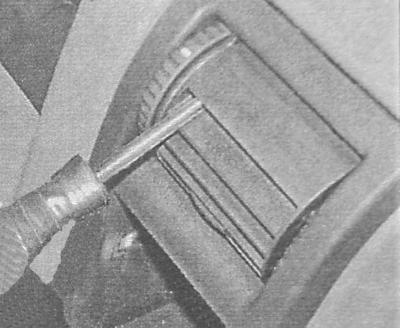
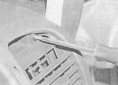
3. Remove the mat, then use a screwdriver to release the top and bottom clips.
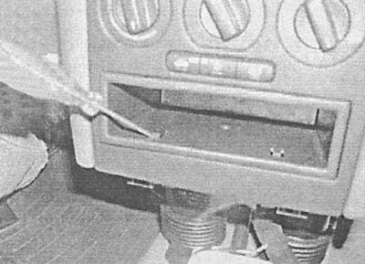
4. Release from the panel of devices a box for trifles.
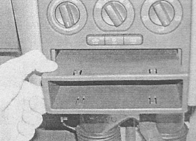
5. Remove the radio and its mounting box (see chapter Onboard electrical equipment). On models equipped with a navigation system, remove the last (see chapter Onboard electrical equipment).
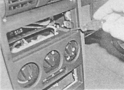
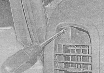
6. Release the latches of the heater operation control handles with a screwdriver through the hole formed and remove them from the control panel.
7. Turn out the lower fixing bolts, accurately remove a decorative slip from the instrument panel.
8. Then disconnect the electrical wiring from the multifunction display assembly.
9. Remove the hazard switch (see chapter Onboard electrical equipment) and disconnect its wiring. If necessary, remove the fixing screws and remove the multifunction display from the panel.
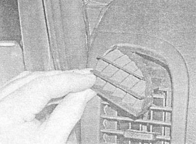
10. Remove the lighting control switch located on the driver's side of the instrument panel (see chapter Onboard electrical equipment). Turn out fixing screws and remove the deflector of a lateral air duct and the switch from the panel of devices.
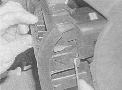
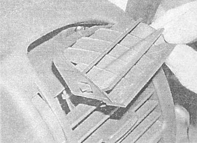
11. After turning the deflector down through the fixed position, access to the mounting screws through its grille should open.
12. If the deflector is tight, remove the screws through the grille, then release the side clips and rotate the deflector before installation.
13. Release the deflector from the instrument panel and remove the screws from it.
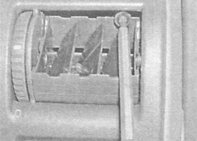
14. Disconnect the electrical wiring from the lighting control switch housing and lower the latter down.

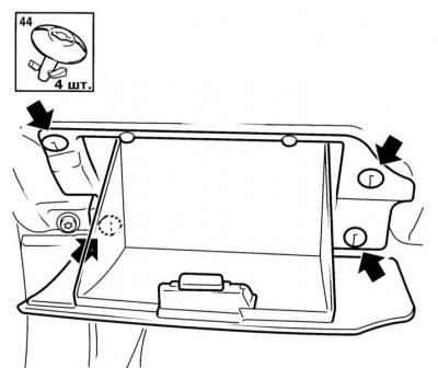
15. Remove the glove box (see Removal and installation of a ware box).
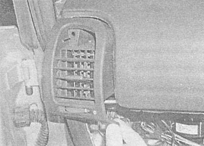
16. Turning down the deflector of the right side air duct, unscrew the fixing screws through its grille.
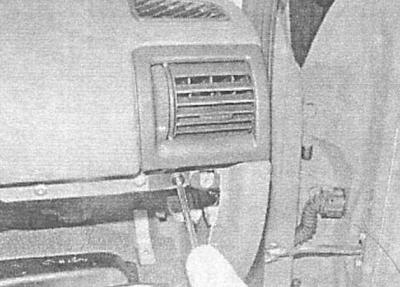
17. Turn out also a bolt of fastening of a deflector and remove the last from the panel of devices.
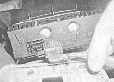
18. Disconnect the electrical wiring from the passenger airbag module through the opening for installing the glove box - try not to damage the terminals of the connector.
19. Remove the steering wheel (see chapter Suspension and steering). Remove from the panel of devices the left lower section of furnish.
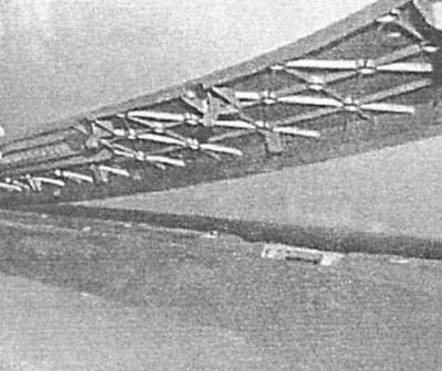
Scheme of installation of the lower sections of the instrument panel trim
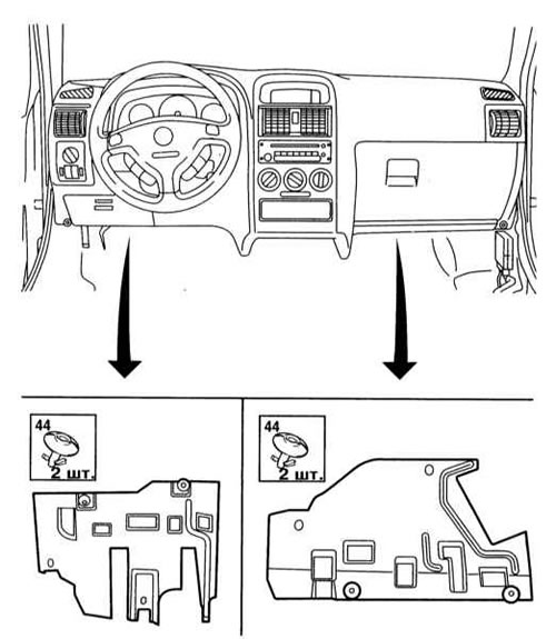
20. Turn out fixing screws and remove the top and bottom sections of a casing of a steering column (see chapter Suspension and steering).
21. Remove paddle shifters (see chapter Onboard electrical equipment).
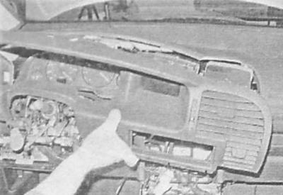
22. Remove the instrument cluster (see chapter Onboard electrical equipment).
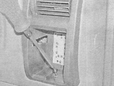
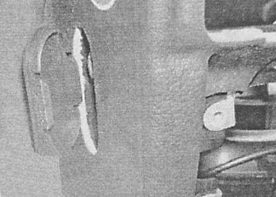
23. Remove the box for small items on the left side of the instrument panel.
A - The layout of the latches for fastening the driver's box for small items
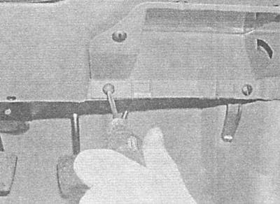
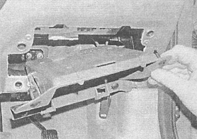
B - Removing the fixing screws
C - Removing the box for small items from the instrument panel
A.
B.
C.
24. In order to expand the working space, remove both front seats (see Removal and installation of front seats).
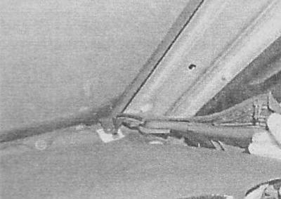
25. Carefully remove the inner sills, unscrew the fixing screws and remove the front corner sills.
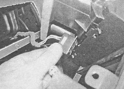
26. Disconnect the electrical wiring from the rear of the instrument panel - try to remember the route of the wiring harnesses.
27. Remove the right lower section of the instrument panel trim (see Removal and installation of interior trim panels) and a sleeve for supplying air to the passenger footwell.
28. Separate the deflector of the air supply sleeve from the instrument panel for blowing the windshield.
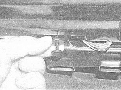
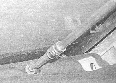
29. Under the windshield, unscrew the three screws securing the front panel to the bulkhead of the engine compartment - the side screws are covered with plastic plugs.
A - Front instrument panel mounting screws
B - Side screw of fastening of the instrument panel (plastic cap removed)
A.
B.
30. Make sure that all electrical wiring is disconnected and nothing prevents the removal of the instrument panel.
31. Together with an assistant, carefully separate the panel from the bulkhead of the engine compartment and carefully remove it from the passenger compartment.
32. Installation is carried out in the reverse order. Check for correct wiring. A description of the installation procedures for the side air duct deflectors is given in Chapter Cooling, heating systems.
Models Zafira
1. Disconnect the negative cable from the battery. Wait at least one minute for the SRS self-contained power supply capacitor to discharge before proceeding with the work ahead.
2. Remove the center console and ashtray (see Removal and installation of a ware box).
3. Remove the heater control panel (see chapter Cooling, heating systems).
4. Remove the steering wheel (see chapter Suspension and steering).
5. Remove paddle shifters (see chapter Onboard electrical equipment).
6. Remove the ignition switch (see chapter Onboard electrical equipment).
7. Remove the radio and its mounting box (see chapter Onboard electrical equipment). On models equipped with a navigation system, remove the last (see chapter Onboard electrical equipment).
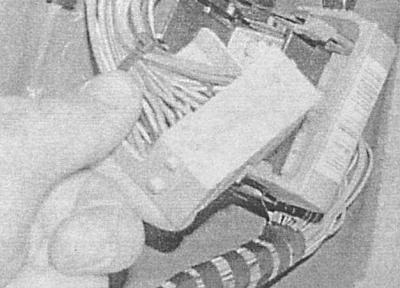
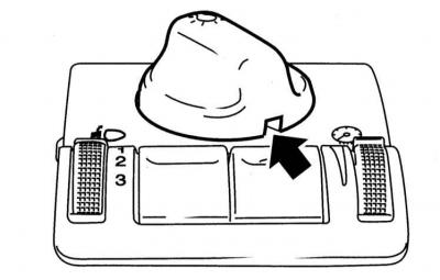
8. Using a small screwdriver, release the latches and remove the light control switch.
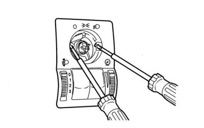
9. Passing a couple of small screwdrivers into the hole for the installation of the switch, release the latches and remove the switch panel - note that the electrical wiring connector remains inside the instrument panel.
10. Remove the fuse box cover.
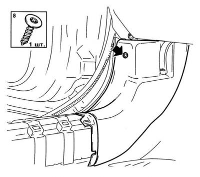
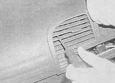
11. Remove the upper section of the side deflector grille from the outside of the instrument panel, remove the screws securing the instrument panel trim, - the entire screw above the shield, one screw in the upper outer corner, one screw inside the upper inner corner grille and four screws at the bottom.
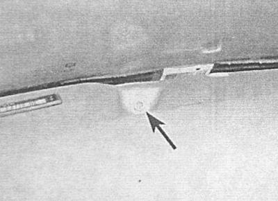
A - Removing the upper section of the side deflector grille
B - Removing the side screw securing the instrument panel trim
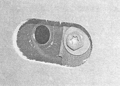
C - The inner screw can be turned out through the deflector grille
A.
B.
C.
12. Remove from the panel of devices a decorative slip and disconnect electroconducting.
13. Remove the instrument cluster (see chapter Onboard electrical equipment), - do not forget to disconnect the electrical wiring.
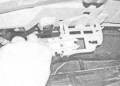
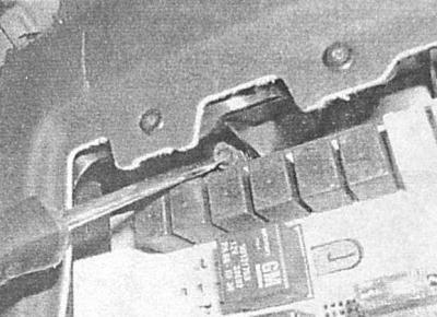
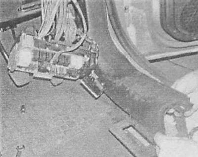
14. Give the nut and screw of the fuse mounting block, release the wiring harness from the holder inside the hole for installing the instrument panel and release the plastic clamp.
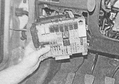
15. Remove the mounting block and move it aside.
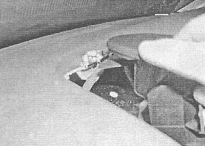
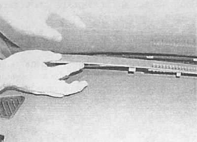
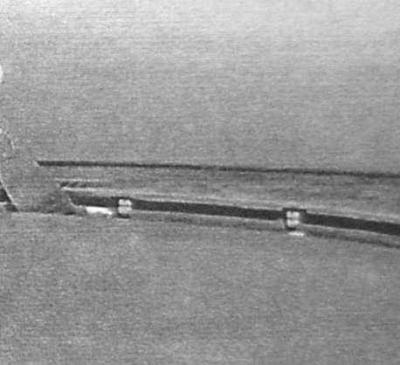
16. Prying with a slotted screwdriver with a wide sting (or spatula), carefully remove the front trim panel under the windshield from the instrument panel.
A - Releasing the clips of the front instrument panel trim
B - Removing the front trim from the instrument panel
A.
B.
17. Remove plastic plugs, turn out fixing screws and remove decorative overlays from racks A.
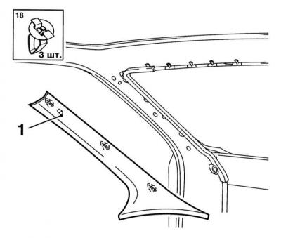
18. Also remove the outer trim sections on both sides of the instrument panel.
19. Remove the front side upholstery panels on both sides of the passenger compartment, then remove the lower trim panels from the A-pillars.
20. Remove the glove box (see Removal and installation of a ware box).
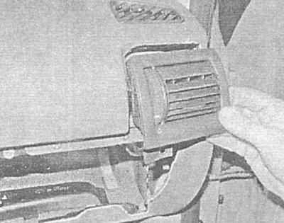
21. Remove the right air duct deflector.
22. Turn out fixing screws.
23. Remove the deflector housing.
24. Remove the lower sections of the instrument panel trim (see Removal and installation of the center console), release the clips and remove the lower air ducts of the heating / ventilation systems of the passenger compartment.
25. Disconnect the connectors of the electrical wiring laid under the instrument panel - try to remember the order of connection and the route of laying the harnesses.
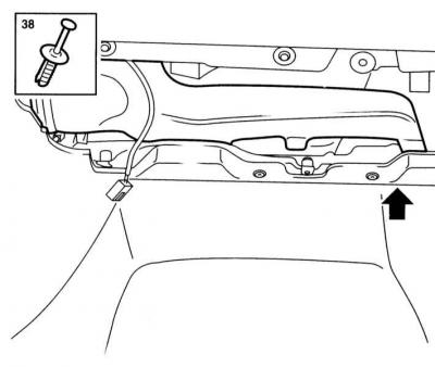
26. Remove plugs and turn out screws of fastening of the panel of devices. Also remove the seals from the door openings in the area of the instrument panel.
A - Removing the front screws securing the instrument panel
B - Mounting screws are under plastic plugs
A.
B.
27. Together with an assistant, carefully separate the instrument panel from the bulkhead of the engine compartment and remove it from the passenger compartment.
28. Installation is carried out in the reverse order. Check for correct wiring. A description of the installation procedures for the side air duct deflectors is given in Chapter Cooling, heating systems.
Visitor comments