
Driving mode select lever position sensor
1. The sensor is a multi-function switch that functions as a reverse light switch and starter interlock, and controls the illumination of the drive selector lever panel. If the driving mode panel illumination or reversing lights are malfunctioning, or the engine starts in other than P and N positions, the sensor is probably defective. If adjustment fails to resolve the problem, replace the sensor assembly.
Removing
2. Place the drive mode selector lever in position N. Apply the handbrake, then jack up the rear of the vehicle and support it on axle stands.
3. Loosen and remove the bolts securing the front exhaust pipe/catalytic converter to the intermediate section of the system (see related section), and separate the flange connection; on models with a 6-cylinder engine, disconnect both the left and right connections. Unclip the thermal insulation from the bottom of the car to gain access to the center bearing of the driveshaft.
4. Loosen and remove the two bolts securing the driveshaft center bearing bracket to the vehicle body (see Section 8). Remove washers (where available), located between the body and the bracket.
5. Trace the wiring from the sensor and disconnect it from the connector. Unclip the connector from the transmission case wall so that it can be removed along with the sensor. If the connector retaining bracket is broken during removal, purchase a new one.
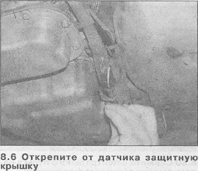
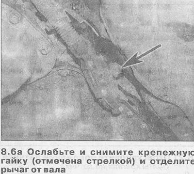
6. Unfasten the protective cover from the sensor, then unscrew the fixing nut and separate the operating lever from the transmission shaft (see illustrations).
7. Support the transmission with a jack by placing a piece of board between them and raise the jack to transfer the weight of the transmission onto it.
8. Loosen and remove the bolts securing the transaxle rear hanger cross member to the vehicle body.
9. Slightly lower the transmission to gain access to the sensor mounting bolts. Do not put too much stress on the driveshaft and engine components and have a second person check to see if anything is pinched between the rear of the engine and the bulkhead.
Attention! On 4-cylinder engines with one overhead camshaft (SOHC) you may have to remove the ignition control module assembly to get the required clearance (see related section).
10. Loosen and unscrew the fastening bolts and remove the sensor from the driver roller. Inspect the roller seal for leaks and replace if necessary (see chapter 6).
Installation
11. Before installing, make sure that the driver roller is still in neutral position (N). If there is any doubt about this, connect the operating lever to the roller and slide the lever all the way back (P position), and then move it forward two marks.
12. If a new sensor is being installed, place it on the roller, then insert the mounting bolts and tighten them with the tightening torque specified in the Specifications. Note that the sensor position has already been adjusted by the sensor manufacturer. The sensor is held in position by a seal, which will be destroyed when the lever is first moved.
13. If installing the old sensor, place it on the roller, then install the mounting bolts. Adjust the position of the sensor as described in paragraph 21, and then tighten the mounting bolts with a tightening torque regulated specifications.
14. Connect the transmission operating lever to the drive shaft, then install the mounting nut. Tighten the nut with a torque specified specifications, then attach the protective cover with staples.
15. Connect the wiring connector, then staple it to the transmission unit and lift the unit into working position.
16. Remove all traces of the blocking composition from the threads of the bolts securing the transmission rear suspension cross member to the body. Apply a few drops of blocking compound (Opel recommends using compound 1510181) on the thread of each bolt, then install the bolts and tighten them with a tightening torque regulated specifications.
17. Align the bracket of the central bearing of the driveshaft with the place of its attachment to the body, placing all the necessary washers under it (where there are). Install the bracket mounting bolts and tighten them with a tightening torque regulated specifications.
18. Install thermal insulation and restore exhaust system flange connection (see related section), then lower the vehicle to the ground.
Adjustment
Attention! Before adjusting the position of the sensor, check the adjustment of the driving mode switching rod (see chapter 3). You will need a short metal rod with a diameter of 2.0-2.3 mm.
19. Place the driving mode selector lever in position N. Apply the handbrake, then jack up the rear of the vehicle and place it on axle stands.
20. Unfasten the protective cover from the sensor, then unscrew the fixing nut and separate the lever from the transmission shaft.
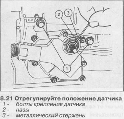
21. With the transmission in neutral, the notch on the sensor should line up with the notch on its inner ring. Test it by inserting a metal rod (see illustration). If adjustment is necessary, loosen the sensor mounting bolts and turn it in the desired direction, then re-tighten the bolts.
22. Connect the operating lever to the roller and tighten the fixing nut with a tightening torque regulated specifications.
23. Attach the sensor cover with brackets, then lower the vehicle to the ground.
Sport mode switch
Attention! You will need a soldering iron and solder.
Removing
24. Unfasten the protective cover of the drive mode selector lever from the central console.
25. Push the switch out of the upper end of the lever by inserting a suitable metal rod into its hole.
26. Apply identification marks to the switch terminals and wires, then carefully unsolder the wires and remove the switch.
Installation
27. Solder the wires to the switch terminals using the marks made prior to removal.
28. Push the switch into working position, then attach the lever guard with the brackets.
Winter mode switch
Removing
29. Unfasten the protective cover of the drive mode selection lever from the central console.
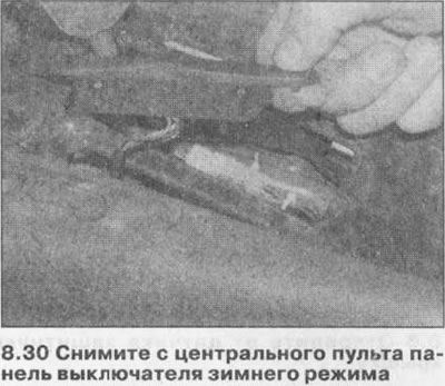
30. Push the switch panel behind the center console out of its working position. Disconnect the electrical wiring connector as soon as it becomes available (see illustration). Separate the switch and panel.
Installation
31. Install in reverse order.
Function switch «kickdown»
32. Function switch «kickdown» mounted in the throttle cable and cannot be removed and replaced separately. Removal and installation of the cable is described in Section 4A. Drive Lever Latch Switch
Attention! When installing, use new switch mounting brackets.
Removing
33. Remove the central console (see related section), then move the driving mode selector lever to the P position.
34. Loosen and unscrew the fixing nuts and bolt, then remove the front and rear brackets for the rear air duct of the interior heating / ventilation system. Unfasten the air duct and move it away from the driving mode selector lever.
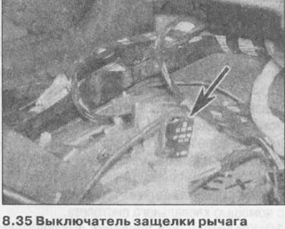
35. Disconnect the electrical wiring connectors, then wring out the mounting brackets and remove the switch from the lever mounting plate (see illustration).
Installation
36. Install in reverse order using new brackets.
Solenoid latch block drive selector lever
Removing
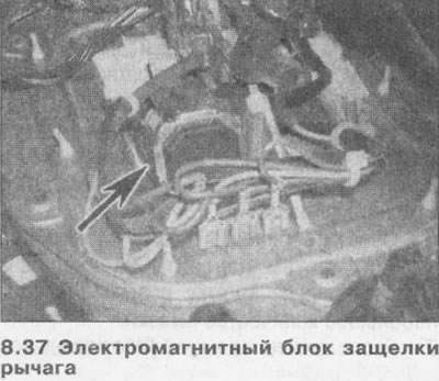
37. Remove the driving mode select lever as described in Chapter 5 (see illustration).
38. Disconnect the solenoid box ground strap from the arm mounting plate and carefully separate the box wiring from the main connector.
39. Loosen the mounting screws and remove the unit from the mounting plate.
Installation
40. Install in reverse order. Make sure the solenoid block is properly engaged with the latch.
Ignition key release switch
Attention! When installing, use new switch mounting brackets.
Removing
41. Follow the steps described in paragraphs 33 and 34.
42. Disconnect the drive mode selector lever main wiring connector, then carefully separate the ignition key release switch wiring from the back of it. Disconnect the switch ground strap from the lever mounting plate.
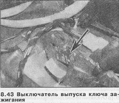
43. Wring out the mounting brackets and remove the switch from the car (see illustration).
Installation
44. Install in reverse order using new mounting brackets.
Electronic control device (ECU)
Removing
45. Disconnect the negative wire from the battery.
46. The ECU is behind the dashboard on the right.
47. Remove the glove compartment (see related section).
48. Remove the nuts securing the ECU to the rack, then carefully lower the ECU from its working position. Release the mounting bracket and disconnect the electrical wiring connector, then remove the ECU from the vehicle.
Installation
49. Install in reverse order. If a new ECU needs to be installed, have your Opel dealer code the unit according to your car's engine type.
Transmission Output Speed Sensor
Removing
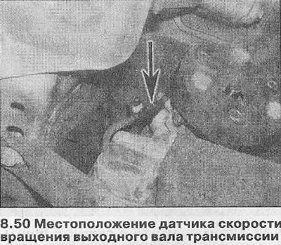
50. The output shaft speed sensor is installed at the rear of the transmission, above and to the left of the driveshaft flange (see illustration).
51. To gain access to the sensor, apply the handbrake, then jack up the front of the vehicle and place it on axle stands.
52. Disconnect the electrical wiring connector and wipe the area around the sensor.
53. Turn off a bolt of fastening and remove the gauge from transmission. Remove the sensor O-ring - it must be replaced.
Installation
54. Install a new O-ring into the sensor groove and lubricate it with transmission fluid.
55. Place the sensor in the working position, then install the fastening bolt and tighten it with the tightening force regulated by the Specifications. Connect the electrical harness connector, then lower the vehicle to the ground.
Transmission solenoid valves
56. Removal and installation of valves must be entrusted to an Opel dealer.
Visitor comments