
Removing
1. Block the rear wheels, apply the handbrake and place the drive mode selector lever in position N. Jack up the front of the vehicle and place it securely on axle stands. Loosen the mounting screws and remove the bottom cover from under the engine. Disconnect the negative cable from the battery.
Attention! On models with anti-theft system Opel (ATWS) You must remove the negative cable from the battery within 15 seconds of turning off the ignition to prevent the alarm from triggering.
2. Unfasten the front end of the propeller shaft from the transmission flange (see Section 8) and remove the vibration damper (where available). Move the propeller shaft to the right of the transmission unit and tie it to the bottom of the vehicle.
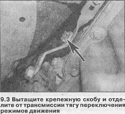
3. Pull out the mounting brackets, separate the drive mode shift rod from the transmission unit and lever and remove it (see illustration). Be careful not to lose the lever pivot bushings.
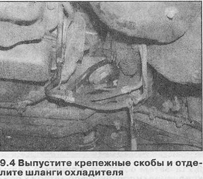
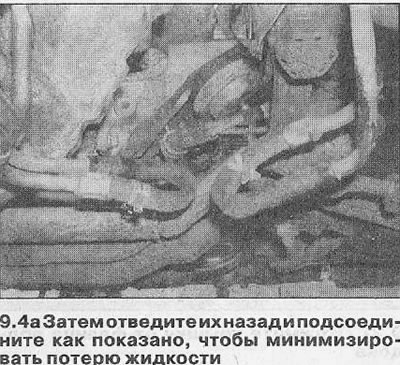
4. Locate the hoses connected to the transmission fluid cooler tubes coming out of the block. Clean off any dirt, then loosen the mounting clamps and disconnect both hoses. Minimize fluid loss by folding hoses back and connecting securely to adjacent tubing (see illustrations).
5. Disconnect the wiring connector from the transmission output shaft speed sensor (see illustration 8.50), located at the back of the block. Separate the sensor wiring from the transmission.
Cars with 4-cylinder engine
6. On engines with one overhead camshaft (SOHC) disconnect the wiring connector from the ignition control module (see related section). Loosen and remove the module bracket mounting bolts, marking the location of the engine lifting lug, then release the electrical wiring. Remove the module and bracket from the cylinder head. Release the high voltage wiring from the mounting brackets and move the assembly away from the transmission block.
7. On all models, disconnect the oxygen sensor wiring connector from the transmission unit and disconnect it.
8. Loosen and remove the bracket bolt of the front section of the exhaust system, then unscrew the bolts securing the front section to the intermediate section and separate them from each other.
9. On solid sump models, loosen and remove the bolts securing the brackets to the transmission case and cylinder block walls. Remove both brackets from the engine, then remove the lower torque converter cover from the transmission case base.
10. On models with a two-piece sump, remove the cover from the sump flange to gain access to the drive plate bolts.
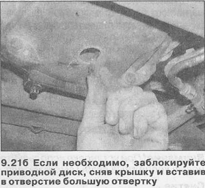
11. Loosen and remove the visible bolts securing the torque converter to the drive plate, then use the socket and extension rod to turn the crankshaft pulley and unscrew the remaining bolts (just six bolts). To lock the disc, remove the cap from the base of the torque converter housing and insert a large screwdriver into the hole.
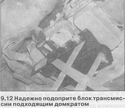
12. Support the transmission with a jack by laying a piece of board between them, and raise the jack to transfer the weight of the transmission to it (see illustration).
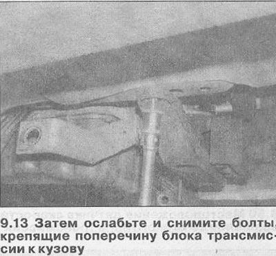
13. Loosen and remove the bolts securing the transaxle rear suspension cross member to the vehicle body (see illustration).
14. Slightly lower the transmission block and disconnect the breather hose from the top wall of the block.
15. Trace the wiring from the drive mode select lever position sensor and disconnect its connector. Unclip the connector and move it away from the transmission case. If the connector retaining bracket is broken during removal, purchase a new one.
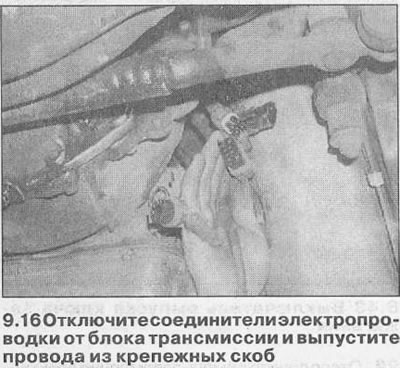
16. Release the mounting brackets and disconnect the electrical wiring connectors from the transmission housing wall (see illustration). Release all electrical wiring from the mounting brackets, having previously marked how it runs, and take the wires away from the transmission.
17. Loosen and remove all bolts securing the transmission housing to the engine! Note the location of each bolt and bracket to facilitate subsequent installation. Also make sure that you have disconnected and removed all components from the transmission so that they do not interfere with the removal procedure.
18. To prevent the torque converter from falling out when removing the transmission, push it fully into the crankcase.
19. Move the jack and transmission back to remove the block from the mounting pins. Gently lower the jack and remove the block from under the vehicle. Remove the dowel pins from the transmission or engine if they are loose and store them away from the work area.
Vehicles with a 6-cylinder engine
20. Remove both front sections of the exhaust system (see related section).
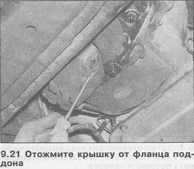
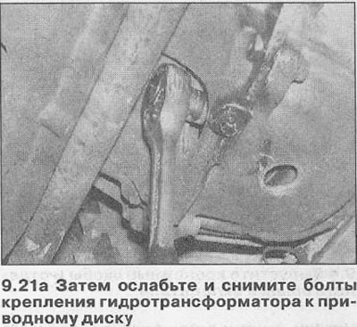
21. Remove the cover from the sump flange to gain access to the torque converter mounting bolts. Loosen and remove the visible bolts securing the torque converter to the drive plate, then use the socket and extension rod to turn the crankshaft pulley and unscrew the remaining bolts (just six bolts). To lock the disc, remove the cover from the base of the torque converter housing and insert a large screwdriver into the hole (see illustrations).
22. Remove the transmission as described in paragraphs 12-19.
Installation
23. Install in reverse order, paying attention to the following.
- A) If a new transmission unit is being installed, drain the coolant and purge the coolant lines using low pressure air.
- b) Check the torque converter center pin and crankshaft bushing for damage or wear. Clean off dirt and rust, then lubricate the bushing and pin with a small amount of molybdenum grease (Opel recommends compound 19 48 568).
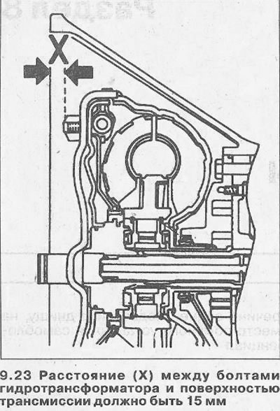
- V) Before installation, check that the torque converter is properly engaged with the transmission by measuring the distance from the torque converter-to-drive plate mounting bolts to the transmission mating surface. It should be 15 mm (see illustration).
- G) Place the dowel pins each in their original position and install the transmission. Be very careful not to let the block hang with all its weight on the torque converter. Install the fastening bolts and tighten them with the tightening force regulated by the Specifications.
- d) Align the torque converter with the drive plate, then install its mounting bolts and tighten them only lightly for now. Working in a diagonal sequence, tighten the bolts to the torque specified in the Specifications.
- e) Make sure transmission wiring/hoses are routed correctly and attached with all brackets.
- and) Remove all traces of blocking compound from the threads of the bolts securing the transmission rear suspension cross member to the body. Apply a few drops of fresh blocking compound (Opel recommends compound 15 10 181) on the threads of each bolt, install them and tighten them with the tightening torque specified in the Specifications.
- h) Tighten all nuts and bolts to the specified torque (where given).
- And) Finally, fill the transmission with the type and amount of fluid specified in the Specifications (see chapter 2) and adjust the drive shift linkage as described in Chapter 3.
Visitor comments