
Selector Lever Position/Start Permit/Reversing Lights Switch
This combined sensor-switch is responsible for the operation of the reverse lights, provides the ability to start the engine only in certain positions of the selector lever («R» And «N»), and also monitors the operation of the indicators on the control panel. In case of failure of any of the listed functions, the switching mechanism should be adjusted. If the adjustment does not give the desired results, replace the sensor-switch.
Removing
1. Set the selector lever to position «N». Apply the parking brake, jack up the rear of the vehicle and place it on jack stands.
2. In order to provide access to the sensor-switch, remove the battery from the installation tray (see chapter Engine electrical equipment).
3. Release the latch (if provided) and carefully disconnect the selector cable from the AT lever. Give a fixing nut and remove the lever from a shaft of the AT selector.
4. Walk along the wiring harness from the sensor-switch to the contact connector and disconnect the latter, after releasing the latch from its housing.
5. On AF20 transmissions remove the measuring probe, give the fixing nut and remove the probe guide tube from the AT crankcase, the sealing element of the tube must be replaced without fail.
6. Bend the lock washer (if provided), give the main nut and remove the washers from the AT selector shaft.
7. Turn out bolts of fastening of a plate of switches and a plait of electroconducting, having pulled up, remove switches.
Installation
1. Before installing, make sure that the selector lever shaft is in the neutral position - if you are not sure, put the selector lever on the shaft and slide it all the way back (into position «R»), then move forward two clicks.
2. Install the sensor-switch on the transmission shaft, install the electrical wiring support bracket. Screw in the mounting bolts, tighten them until only by hand.
3. Install the washers and screw the main nut onto the selector shaft. Tighten the nut to the required torque. Secure the nut by bending the end of the lock washer.
4. Adjust the sensor-switch (see below).
5. Connect the electrical wiring - follow the correct laying of the harness.
6. On AF20 transmissions put a new sealing element into the hole in the AT crankcase, insert the measuring guide tube and securely tighten the nut of its fastening. Insert the dipstick into the tube.
7. Establish the selector lever on a shaft and tighten a nut of its fastening with the demanded effort. Connect the selector cable to the lever pivot.
8. Reinstall the battery and check the operation of the sensor-switch, - if necessary, adjust the selector cable (see Gear selector adjustment).
Adjustment
Before adjusting the sensor-switch, make sure that the selector cable is correctly adjusted (see Gear selector adjustment).
1. Follow the procedures Withdrawals, pp. 1-3 (see above).
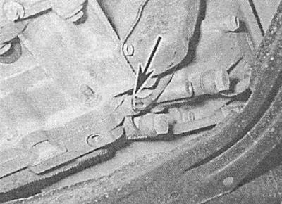
2. Shift the transmission to «N», - the selector shaft should turn in flats parallel to the marking on the sensor-switch housing. If necessary, loosen the sensor-switch mounting bolts and adjust the position of the latter accordingly. Having achieved the desired result, tighten the bolts with the required force.
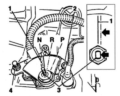
1 - Marking of the assembly of the sensor-switch
2 - Mounting bolt
3 - Selector shaft
4 - Mounting bolt
3. Install the selector lever on the shaft and tighten the fixing nut to the required torque. Connect the end of the selector cable to the lever and (with appropriate equipment) secure it with a retainer.
4. Reinstall the battery and check the correct operation of the sensor-switch - if the adjustment does not give the desired results, replace the sensor-switch.
Sport mode switch
You will need a soldering iron, solder and acid-free solder paste.
Removing
1. Remove the selector lever assembly (see Removal and installation of assembly of the lever of the selector АТ).
2. Push the switch out of the top of the lever by inserting a piece of welding electrode through the special hole.
3. Clearly mark the switch and the wiring connected to it, then unsolder the wires from the switch terminals and remove the latter - the wiring harness can be pulled out from the base of the lever if necessary.
Installation
1. Solder the wires to the switch terminals - make the connection in accordance with the marking applied during the dismantling process.
2. Gently place the switch in its original place, then install the selector lever (see Removal and installation of assembly of the lever of the selector AT).
Winter mode switch
Removing
1. Remove the center console (see chapter Body). Remove the two fixing screws from the back of the cover and remove the latter from the lever assembly.
2. Release the latches and remove the indicator panel from the arm assembly support bracket.
3. Walk on a plait of electroconducting from the switch to a contact socket and disconnect the last. Release the switch from the indicator panel and remove it from the vehicle.
Installation
Installation is carried out in the reverse order to the dismantling of the components.
Kickdown activation switch
The sensor-switch is built into the accelerator cable and cannot be replaced individually. A description of the procedure for replacing the cable is given in Chapter Power and exhaust systems.
Electronic control module
Removing
The control module is installed on the right under the instrument panel and attached to the bracket to the air distributor housing.
1. Disconnect the negative cable from the battery before removing the module.
2. Remove the center console (see chapter Body). Remove the left center air duct (see chapter Cooling, heating systems).
3. Detach the module support bracket from the air terminal housing and move the module aside. If the wiring interferes with the retraction of the assembly, cut off the plastic tie that secures the harness. Disconnect the electrical wiring from the module; if necessary, remove the latter from the support bracket.
Installation
Installation is carried out in the reverse order to the dismantling of the components. Check that the electrical wiring is connected correctly.
AT input and output shaft speed sensors
Removing
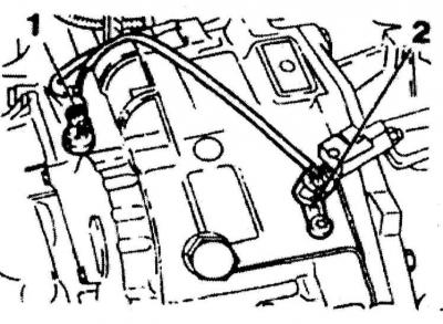
input speed sensor (1) and weekend (2) shafts AT (2.0 l models)
On AF20 transmissions The sensors are mounted on top of the crankcase. The input shaft sensor is in front and closer to the left edge of the transmission, the output shaft is at the rear. On transmissions AF13 and AF17 the sensors are mounted on top at the rear of the crankcase, - the output shaft sensor is above the input shaft sensor.
1. On equipped with transmission AF13 and AF17 models apply the parking brake, jack up the front of the vehicle and place it on jack stands. Remove the left front wheel and the arch protection locker (if provided - see chapter Body). On models with AF20 transmissions in order to provide access to the sensors, remove the battery with the installation tray (see chapter Engine electrical equipment).
2. Disconnect the electrical wiring and clean the sensors and the surfaces of the crankcase adjacent to them.
3. Turn out a fixing bolt and remove the corresponding gauge from transmission, a sealing ring is subject to replacement without fail.
Installation
1. Having previously lubricated with ATF, put a new sealing ring on the sensor.
2. Insert the sensor into its seat, screw in the mounting bolt and tighten it to the required torque. Restore the original wiring connection.
3. On 2.0 l models (AF20 transmission) install the battery. On equipped with transmission AF13 and AF17 models install wheel arch locker (if filmed) and left front wheel. Lower the vehicle to the ground and tighten the wheel nuts to the required torque.
ATF temperature sensor
Removing
For AF13 and AF17 transmissions, the ATF temperature sensor is supplied complete with wiring harness. To remove the sensor, it is necessary to dismantle the side cover of the transmission, behind which various valves and electromagnetic switches are installed - this is a rather difficult task that requires perfect cleanliness, which is why it will be correctly entrusted to car service specialists. Below is a description of how to remove the sensor from AF20 transmissions fitted to models equipped with 2.0L engines.
1. The sensor is screwed into the front of the transmission housing base - disconnect the negative cable from the battery before removing it.
2. Apply the parking brake, jack up the front of the vehicle and place it on jack stands.
3. Walk from the sensor along the electrical wiring - try to remember the route of laying the harness. Disconnect the electrical wiring and release it from the intermediate clamps.
4. Turn out fixing bolts and remove a cover from the gauge.
A — Bolts of fastening of a case cover AT
B - ATF temperature sensor
A.
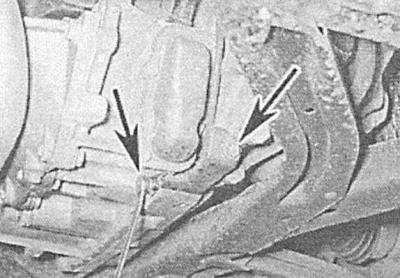
B.
5. Wipe the surface of the AT crankcase adjacent to the sensor.
6. Turn out the gauge and remove it in gathering with a plait of electroconducting. Seal the opening in the crankcase immediately with a suitable plug.
Installation
1. Place a new sealing washer on the sensor, remove the plug and quickly screw the sensor into the hole in the transmission case. Tighten the sensor to the required torque. Wipe up any spilled liquid immediately with a clean rag, then replace the cover and tighten the cover bolts securely.
2. Lay the wiring harness properly and secure it in all provided intermediate clips.
3. Lower the car and connect the negative wire to the battery. Check ATF level, correct if necessary (see chapter Current service).
Visitor comments