
2. Remove the front wheel.
3. Remove the cotter pin from the gear nut or nut retainer at the end of the drive shaft. Unscrew the nut. This nut is very tight and you will need a long knuckle to loosen it. Have an assistant press the brake pedal or screw a lever in place of the two wheel bolt holes (as shown in fig. 7.1) to prevent the drive shaft from turning. There is no need to remove the brake caliper.
4. Disconnect the anti-roll rod from the lower control arm.
5. Disconnect the lower control arm support from the body side member (Chapter 10) and, while it hangs on its ball joint, move the control lever aside.
6. Now you will need a tool that can be inserted between the transmission boot and the drive shaft inner joint. If you don't have an official tool, a flat piece of steel with a good bevel on one end will work as a substitute. Insert such a tool into the gap between the joint and the case in order to disconnect the shaft latch ring from the differential. Be prepared for some oil spillage and plug the hole (even with the help of a piece of cloth) to prevent oil loss and dirt entry (photo).
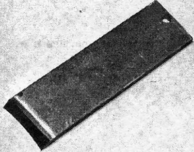
Photo 2.6A Suitable tool for removing the drive shaft.
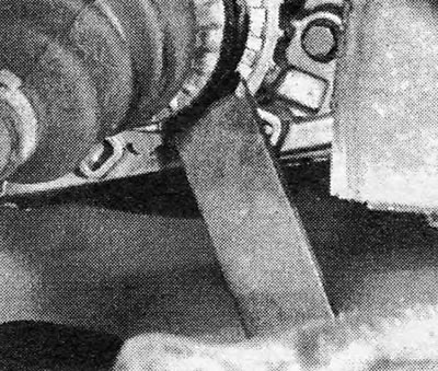
Photo 2.6B Disconnecting the drive shaft from the differential.
7. It should now be possible to push the drive shaft out of the hub using your fingers. If this is not the case, then use a hub extractor (photo).
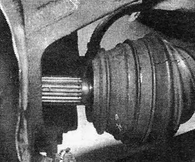
Photo 2.7 Drive shaft disconnected from hub holder.
8. When removing the left hand drive shaft, it may be difficult to use a suitable tool to disconnect it from the transmission. In this case, take a long steel rod and, holding the edge of the hinge, push it out.
9. Models manufactured after October 1982, particularly 1.6, 1.8 and 2.0 automatic models, have shafts that incorporate a modified internal joint. This type of joint does not contain a stopper to limit the sliding feed inside the joint. Therefore, when removing or working on this type of drive shaft, great care must be taken not to pull on the shaft, which will cause the joint parts to separate and render the entire shaft unusable.
10. On manual transmission models 1.6, 1.8 and 2.0, the longer right-hand drive shaft has a two-piece weight that acts as a torsional vibration absorber. If you remove it for any reason, it is important that when reinstalling the distance between the inner end of the outer hinge bellows and the outer surface of the weight is 260mm (10.24 inches).
11. Do not move the machine on its wheels while one or both drive shafts are removed from their hubs. If this precaution is not taken, the front wheel bearings may be damaged.
12. The drive shaft-hub nut should be replaced whenever it has been disturbed.
13. Before reinstalling the drive shaft, make sure that the contact surfaces of the shaft joint and the hub bearing are absolutely clean (Pic. 7.3). Apply some grease to the keyways of the shaft and insert it into the hub holder. Tighten the shaft nut using your fingers. Install a new snap ring onto the inner end of the drive shaft (photo).
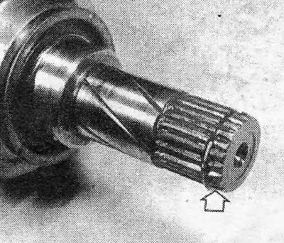
Photo 2.13 Latch ring of the drive shaft internal joint (indicated by an arrow).
14. Insert the inner end of the drive shaft into the transmission all the way (photo).
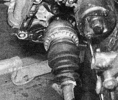
Photo 2.14 The drive shaft is inserted into the gearbox.
15. Now use a screwdriver, grasping the welding edge, not the metal cover, and push the drive shaft into the differential until the retaining snap ring is firmly in place. Pull the drive shaft to check the clutch (photo).
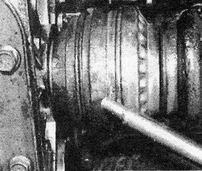
Photo 2.15 Attaching the drive shaft joint to the gearbox.
16. Reconnect the suspension arm and anti-roll rod as indicated in Chapter 10 and tighten all nuts and bolts to the specified torque values.
17. Tighten the new drive shaft/hub nut to the specified torque in stages (see Specifications).
18. Install the nut stopper (if it is installed) and insert a new cotter pin. Bend the ends of the cotter pin.
19. Install the wheels and lower the machine to the ground.
20. Add gear oil (see Chapter 6).
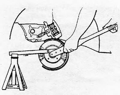
Pic. 7.1.Unscrewing the drive shaft nut.
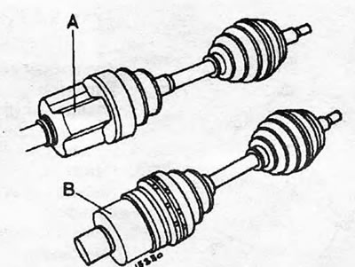
Pic. 7.2. Comparison of internal joints on models with automatic transmission: A - Since 1983; B - Early models.
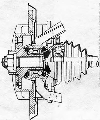
Pic. 7.3. Section of the front hub. Clean the indicated surfaces.
Visitor comments