


2. Raise the front of the car and remove the road wheel (see Chapter 9, Section 3).
3. Disconnect the anti-roll bar end link.
4. Using a suitable tool, disconnect the control bracket ball joint from the short axle holder (see Section 3, paragraph 6) (photo).
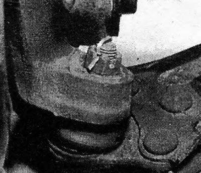
Photo 6.4A Ball joint of the control bracket.
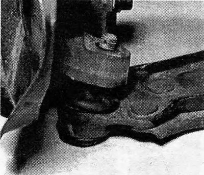
Photo 6.4B The control bracket ball joint is disconnected.
5. Unscrew the control bracket bolts from the support. On some newer models, the control bracket support is extended and is attached to the front crossmember of the body; removing the control bracket from a support of this type is done in a similar way (photo).
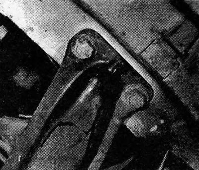
Photo 6.5 Front mount of the long type control bracket support.
6. Assembly is done in the reverse order, but it is necessary to clean the threads under the support bolts from the thread-blocking mixture by screwing a thread-cutting device (M12x1.75) into the holes. Now you must use new bolts. They should already be coated with thread locking compound; just make sure that these bolts are not more than 5 years old, otherwise the mixture will no longer be effective. You can determine the year of manufacture by the numbers on the bolt heads, which represent the last two digits of the year.
7. Keep the control bracket horizontal while tightening the bolts; tighten the bolts to the specified torque value.
8. On the right-hand control bracket on the 1.6 and 1.8 models, a shock absorber weight is installed (Figure 10.7). It is secured with socket head screws (photo).
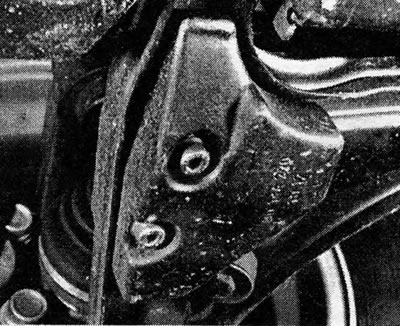
Photo 6.8 Shock absorber weight of the right-hand control bracket.
Material copied from the portal (Opelbook.ru)
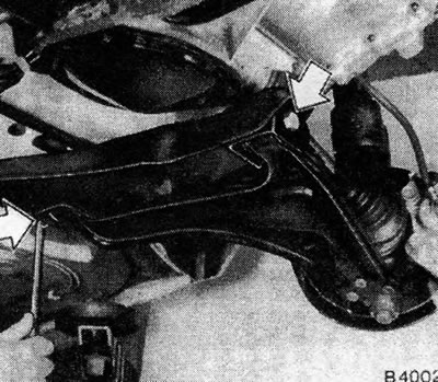
Figure 10.6. Unscrew the control bracket bolts - indicated by arrows
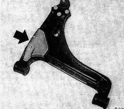
Figure 10.7. Control bracket shock absorber weight - indicated by arrow
Visitor comments