


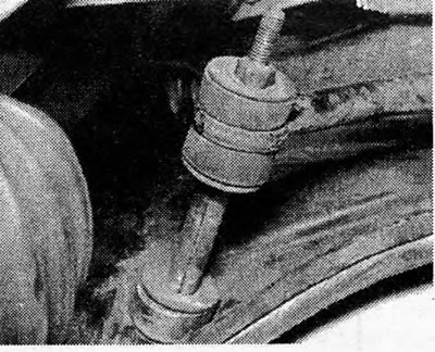
Photo 10.1 Front anti-roll bar end link.
2. Release the control bracket support from the housing as described in the previous Section. Do not remove it completely, but leave it hanging on the central bolt. This will provide enough clearance to remove the anti-roll rod sideways once the rod clamps have been released from the bottom of the hull.
3. Assembly is in reverse order, but follow the procedure described for the support bolts in the previous Section.
4. Tighten the anti-roll bar end link nut to provide the specified compression of the rubber gasket as shown in Figure 10.12.
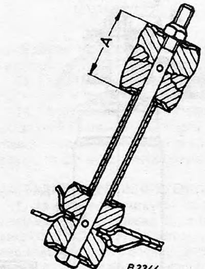
Figure 10.12. Front anti-roll bar end link:A=38.0 mm (1.5 in).
Visitor comments