
All models.
1. The control bracket is usually removed during disassembly of the engine, transmission or drive shaft, and the operations described here are intended to accomplish precisely this purpose. However, if you remove the support for the purpose of replacement or repair, then you first need to disconnect the control bracket from it by unscrewing the corresponding bolts.
2. Raise the front of the car and remove the road wheel.
3. Disconnect the anti-roll rod from the control bracket by unscrewing the nuts on the rod end link.
Short type support - 1.3, 1.6 except GLS
4. Unscrew the two smaller bolts that secure the support to the underbody (photo).
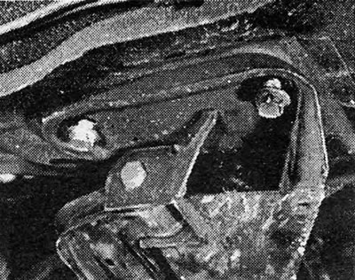
Photo 9.4 The smaller control bracket support bolts have been removed.
5. Unscrew the larger bolt from underneath where it is centered, but do not remove it.
6. The support is located on the position pin and you will now need an extractor to remove it.
7. A suitable tool can be made by modifying the extractor with two legs as shown (photo). An important detail is the shape of the anchor bolt heads, which must be inserted into small rectangular recesses located at the bottom of the support. Then they need to be rotated 90 degrees to give reliable support to the tool (photo).
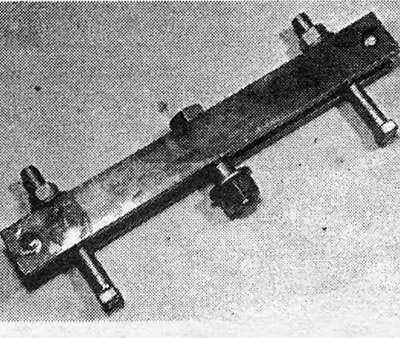
Photo 9.7A Control Bracket Support Removal Tool.
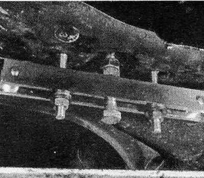
Photo 9.7B Removing the control bracket support.
8. If the extractor bolt is now positioned against the head of the larger mount bolt and you screw it down, this will cause the mount to jump off the dowel and hang on the partially unscrewed center bolt (photo).
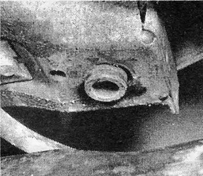
Photo 9.8 Short type control bracket support positioning dowel.
9. Remove the center bolt and lower the support (photo).
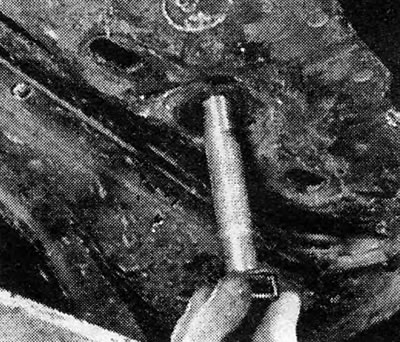
Photo 9.9 Removing the larger control bracket support mounting bolt.
10. Reassemble in the reverse order, but all threaded holes at the bottom must be cleared of old mixture blocking the threads. Always use new bolts that come pre-treated with thread locking compound.
11. Tighten the support bolts to the specified torque (photo).
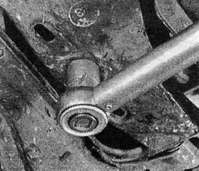
Photo 9.11 Tighten the larger control bracket support mounting bolt to the specified torque.
Long type support - 1.6 GLS and 1.8.
12. On these models, the control bracket support is held in place by six bolts and is not located on a dowel like the short type support just discussed (photo).

Photo 9.12A Center and rear control bracket support bolts (long type).
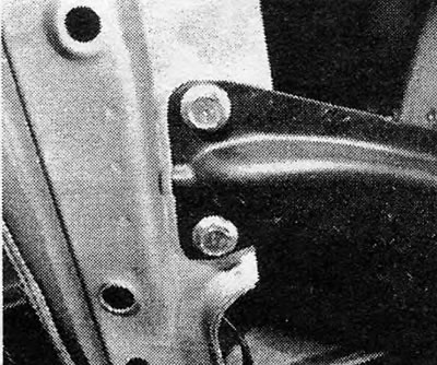
Photo 9.12B Front bolts on control bracket support (long type).
13. Apart from this, and the fact that you do not need any special tools, the removal and installation operations are similar to those just described; but before removing the support, sketch out the support positions front and back to ensure proper assembly later.
14. Bolt threads must be cleaned and coated with fresh thread locking compound before they can be tightened to specified torque values.
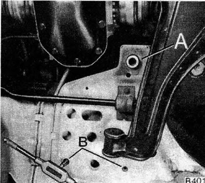
Pic. 10.11. Installing the suspension control bracket support: A - Mounting pin.; B - Cleaning the threaded holes of the mounting bolts.
Visitor comments