
2. The rear axle must be supported, preferably with a trolley jack, and the brake hose rings must be removed from under the housing.
3. Unscrew and remove the axle bolts that secure the locking arms to the bottom (photo).
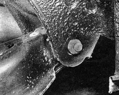
Photo 18.3 Bolt-axle of the rear closing link
4. Lower the lever very slowly and at the same time release the brake hoses and rigid pipes, bending them if necessary to prevent them from being pulled.
5. Once the flexible bushings in the locking arms are clear of the bottom, support the rear axle on the axle stands.
6. Cut off the flange from the flexible bushings with a sharp knife (Pic. 10.30).
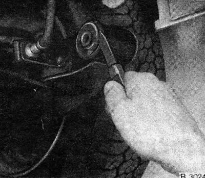
Pic. 10.30. Cutting off the flange from the flexible sleeve of the closing lever
7. Tap around the bushing case to release the bushing.
8. Using the bolt and spacers, remove the bushing from the locking arm. This will be easier if you heat the case to a temperature of 60 to 70 degrees Celsius (140 to 158 degrees Fahrenheit). Do not use an open flame to do this, but heat the case with a soldering iron or rags soaked in boiling water.
9. Lubricate the new bushing and place it in place, but make sure that the bushing is positioned as shown in Fig. 10.32.
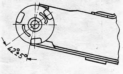
Pic. 10.32. Locking lever flexible bushing location
10. Always replace the bushings on both track links at the same time.
11. Install the bridge by performing the operations in reverse order. Tighten the bolts to the specified torque value - see Section 17, paragraph 11 (A).
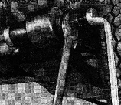
Pic. 10.31. One method for removing and installing the lock lever
Visitor comments