
Removal and installation of the operating lever
1. Raise the car on a lift.
2. On models equipped with xenon headlights, remove the 3 bolts and remove the light range sensor from the left control arm (see resist. illustration).
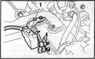
6.2 Sensor (1) xenon headlight range adjustment mounted on the left control arm of the front suspension
3. Check hydraulic arm support (see below).
4. Remove the Tox bolt (see resist. illustration) clamp for attaching the outer ball joint of the lever to the steering knuckle. Turn out an axial bolt of an internal forward support of the operating lever.
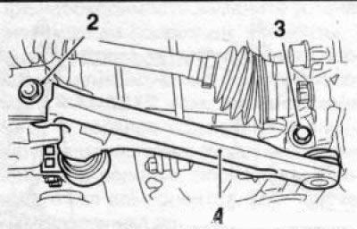
6.4 Control arm mounting bolts (4): 3. Collar of fastening of a spherical support; 2. Internal front support
5. Remove 2 bolts (see resist. illustration) attaching the hydraulic arm support to the subframe. Pull the control lever firmly down and separate the lever from the steering knuckle.
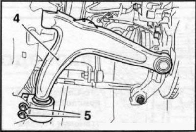
6.5 Bolts (5) control arm hydraulic support mountings (4)
Note: No tool should be used to separate the lever.
6. Remove the control lever.
7. Installation is made in an order, the return to an order of removal. Pre-clean the mating surfaces and bolt holes on the arm and subframe. Only new self-locking bolts should be used for fastening. Initially, the bolts for fastening the inner arm supports to the subframe are tightened by hand, and then, after installing and tightening the bolt of the outer (ball) lever supports, reach with the required force (see specs).
Checking the fit of the hydraulic support
8. Checking the fit of the hydraulic support should be done whenever it is necessary to disconnect the outer (ball) control arm support from the steering knuckle.
9. Raise the car on a lift, or place it on stands.
10. Set the limit on the torque wrench to 30 Nm.
11. Turning the torque wrench clockwise, try to turn the axial bolt securing the hydraulic bearing bushing. The hydraulic support has been set correctly if the axle bolt does not turn with a force of 30 Nm. Otherwise, adjust the fit of the support.
Adjusting the fit of the hydraulic support
12. On models equipped with xenon headlights, when adjusting the hydraulic support of the left control arm, remove the light range adjustment sensor (see illustration 6.2).
13. Disconnect the tie rod end from the corresponding steering knuckle (see Section 15).
14. Remove the axle bolt from the hydraulic bearing bushing (see resist. illustration) and clean the threaded connection of the control arm.
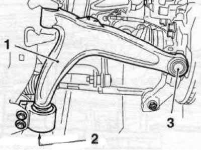
6.14 Axle bolt (2) fixings of the bushing of a hydraulic support: 1. Control lever; 3. outdoor (ball) lever support
15. Turn out a fixing bolt and dress a spherical support of the lever from a rotary fist (see above).
16. Press the shock absorber to the side. Raise and install the control arm so that it is horizontal, while the axis, which can be mentally drawn through the middle of the inner arm supports, should run parallel to the longitudinal beam of the subframe. Be careful not to damage the driveshaft CV joint boot.
17. In this position, screw in a new self-locking bolt securing the hydraulic bearing bushing. Pre-lubricate the threads of the bolt with a fixing compound (e.g. Loctite 243) and tighten the bolt in 2 steps (see specs).
18. Replace and secure all removed and detached components.
Visitor comments