
2. Remove the corresponding wheel and loosen the hub nut (see Section 4).
3. Remove the brake shoe guide and front wheel brake disc (see chapter 9).
4. Check the condition of the hydraulic support of the control arm (see Section 6).
5. Disconnect from a rotary fist a operating lever and a tip of steering draft.
6. Tie the drive shaft with a wire to the body elements and remove the shaft pin from the hub assembly (see chapter 8).
7. Release from the holder on a shock-absorber rack and disunite a socket of electroconducting of gauge ABS.
8. Loosen nuts (see resist. illustration) and remove the lower shock absorber mounting bolts.
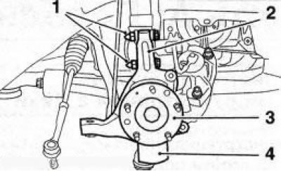
5.8 Removing the steering knuckle (2): 1. Nuts of the lower bolts of fastening of a shock-absorber rack; 3. Hub assembly; 4. Brake guard
9. Remove the steering knuckle (see illustration 5.8) from the shock absorber together with the hub assembly and the brake shield.
10. Clamp the steering knuckle in a vise (see resist. illustration), unscrew the 3 bolts securing the hub assembly and remove the assembly with the brake shield.
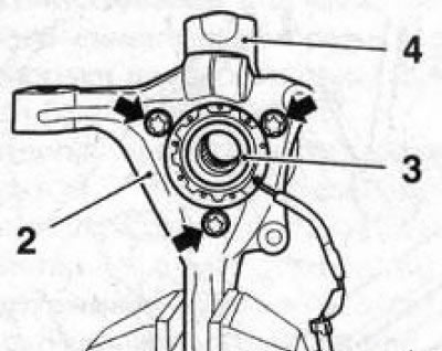
5.10 Bolts (indicated by arrows) hub assembly mountings (3) to the steering knuckle (2): 4. Brake guard
Note: If necessary, the hub assembly can be removed without removing the steering knuckle.
11. Installation is made in an order, the return to an order of removal. Follow all instructions given in the relevant chapters and sections.
Visitor comments