
Note: When installing, use a new ball joint nut locking pin connecting the lower arm to the suspension strut, and (where applicable) a new nut securing the anti-roll bar to the lower control arm.
Removing
1. Where applicable, remove the caps, then loosen the front wheel bolts. Apply the handbrake, then jack up and support the front of the vehicle on axle stands. Remove the front wheel.
2. Loosen and remove the nut securing the end of the anti-roll bar to the lower control arm. Remove concave washers and rubber pads.
3. Remove the locking cotter pin, then loosen the castle nut on the ball joint that connects the lower arm to the suspension strut.
4. Using a special puller, separate the ball joint.
5. Loosen and remove the two pivot bolts securing the lower arm to the subframe (see illustration).
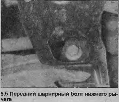
Note that the rear pivot bolt also secures the subframe to the underbody. Both bolts are very tight and will require a long rod to loosen them.
6. Move the lower arm away from the subframe and remove it from under the vehicle.
7. Please note that some 2.0L models are equipped with a vibration damper bolted to the right lower arm. If the right lower arm on such a vehicle is to be replaced, do not forget to move the vibration damper to the new arm.
8. Please note that when installing the lower arm, the metal couplings in the rear mount bushing can be discarded.
9. If there is any sign of damage or deformation of the lower front suspension arm (see around front pivot bolt), replace the lever (you can purchase a new, reinforced modification of the lever from Opel dealers).
10. A new modification of the lower arm, which can be distinguished by the flange on the seam on the front side of the arm, has been installed in series since mid-1993.
11. The modified lower arm and the early version are fully interchangeable. Note that if a new version of the arm is being installed on a model with a lower arm equipped with a vibration damper, the vibration damper should not be converted to the new arm.
Installation
12. Install the lower arm to the subframe.
13. Install the two pivot bolts, then tighten the bolts to the specified torque specifications, while holding the lower arm in a horizontal position. Please note that the rear bolt must be tightened in stages (see specs).
14. Install the ball joint connecting the lower arm to the suspension strut, and tighten the castellated nut with the torque specified specifications. Secure the nut with a new locking cotter pin.
15. Connect the end of the anti-roll bar to the lower arm, remembering that the concave washers holding the rubber pads must face the concave side of the lower arm.
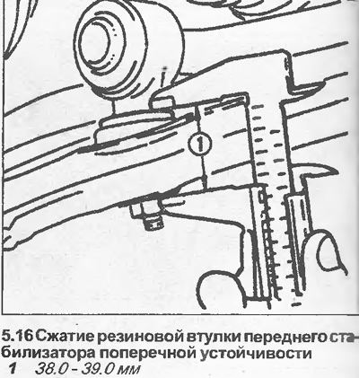
16. Tighten the nuts securing the anti-roll bar to the lower arm to achieve regulated compression of the rubber bushing (see illustration). If necessary, replace rubber bushings.
17. Install the wheel and lower the vehicle to the ground. Finally tighten the wheel bolts and, where applicable, install the wheel cap.
18. Check and, if necessary, adjust the front wheel alignment as described in Chapter 45.
Visitor comments