
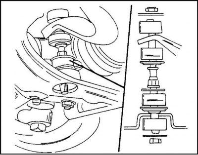
Fastening of the anti-roll bar of the car until the middle of 1995 of release. Left to stabilizer bar, right to transverse arm
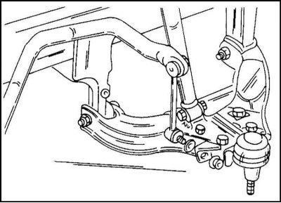
Mounting the anti-roll bar to the transverse arm of the car from the middle of 1995 release
Connecting rods with ball joints are used.
Each end of the stabilizer is attached to the transverse arm with a connecting rod.
The following works are described in the relevant subsections.
Removing
1. Remove the torsion bar.
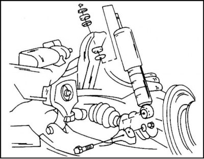
2. Disconnect the shock absorber from the lower transverse arm.
3. Disconnect the connecting rods from the lower transverse arm. This is done depending on the year of manufacture of the car in accordance with Section 4. Attachment details are shown in the illustrations "Mounting the anti-roll bar of the car until the middle of 1995 release" And "Mounting the anti-roll bar to the transverse arm of the car from the middle of 1995 release".
4. Remove the nut from the lower ball joint pin at the steering knuckle and disassemble the connection using a puller.
5. Remove the two bolts and nuts securing the torsion bar from the lower transverse arm.
6. Disconnect the lower wishbone from the chassis. Each control arm rubber bushing is secured with one bolt and nut.
Installation
Installation is carried out as follows:
1. Install the lower transverse link to the chassis and secure both ends of the link with a bolt and nut.
2. Pre-tighten the lever mounting bolts by hand.
3. Attach the guide joint to the lower transverse arm and tighten the nut to 140 Nm.
4. Align the hole in the bolt with the slot in the castle nut and install the cotter pin.
5. Install the torsion bar support on the lower transverse arm and secure with two bolts and nuts.
6. Tighten the bolts to a torque of 116 Nm.
7. Install the anti-roll bar and shock absorber as described above. Keep in mind the year of manufacture of the car. Pay attention to the attachment of the connecting rod to the bottom.
8. Install the torsion bar on the wishbone and chassis.
9. Tighten the bolts/nuts of the transverse arm now.
10. In doing so, first perform the next measurement. Raise the control arm so that the dimension shown in the illustration is 15 mm for a car before mid-1995 and 25 mm for a car from mid-1995. Measure carefully. The rubber support must be correctly clamped.
11. Tighten the bolts and nuts securing the front axle of the suspension arm to a torque of 160 Nm, the rear axle of the suspension arm to a torque of 200 Nm.
12. Carry out other work in the reverse order of removal. In conclusion, check and, if necessary, adjust the clearance.
Replacement of bushings of the cross-section suspension arm
The control arm bushings can be replaced. However, the removal and installation of bushings requires a special tool. It is recommended that this work be carried out in a workshop. You can also press out the bushings using a suitable pipe, washer and bolt. Bushings should not be clogged, they should be pressed in.
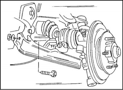
Lower wishbone ball joint
To disconnect the lower joint from the steering knuckle, remove the cotter pin, unscrew the locknut and press the joint out of the steering knuckle using a puller. The hinge is attached to the transverse lever with four bolts and nuts. The new ball joint does not need lubrication. Lubrication in the hinge is already introduced at the factory.
1. When installing the ball joint on the lower transverse arm, carefully pull the protective boot over the edge of the joint housing to ensure a tight connection.
2. Tighten the hinge bolts evenly to 105 Nm.
3. Press the joint into the steering knuckle.
4. Tighten the pivot nut to 105 Nm.
Visitor comments