
Camber, caster, toe and clearance check
Before carrying out any measurement work, the following conditions must be met:
The profile wear of all tires should be approximately the same.
Tire pressure should correspond to the full load of the car.
All rims must be in perfect condition.
The ball bearings of the steering rods and suspension must not have any gaps.
The car must have a set ground clearance (see the following description).
When measuring the geometry of the front wheels, the car must be on a flat area with the same height in the area of the front and rear wheels. A height difference of more than 6 mm is not allowed. The fuel tank must be full and the vehicle must not be loaded with anything.
The steering wheel must be straight during the measurement.
The measurement must be carried out using optical instruments. In the following description, only cases of measurement in emergency situations are considered.
Front suspension height adjustment (clearance)
The height of the front suspension is adjusted using the torsion bar adjusting bolt. The location of the bolt is shown in the illustration. Turning the bolt clockwise increases the suspension height.
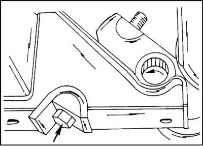
Ride height torsion bar adjusting bolt
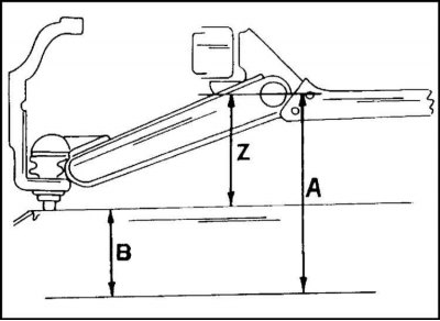
Height is measured as shown. Size "Z" defined as the size difference "A" And "IN". The value obtained must be compared with the target value: The maximum difference between both sides of vehicles produced since mid-1995 is 5 mm.
Camber adjustment
The camber angle can be measured by mechanical means, however an optical instrument is required for an accurate measurement. If the camber is out of range, it can be adjusted.

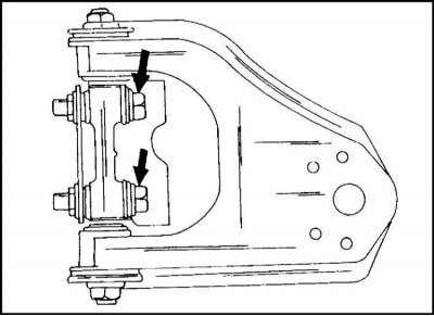
Adjustment is achieved by changing the thickness of the washers between the axle of the upper suspension arm and the cross member bracket.
Adjusting washers are slotted. Once both screws are loosened, they can be removed and replaced.
The collapse of cars must have the values specified in Specifications.
The maximum allowable difference between the parties is indicated in Specifications.
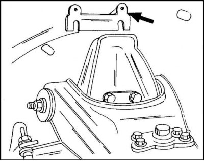
To adjust, unscrew the bolts and nuts securing the suspension arm and remove the washers, as shown in the illustration. The washers are placed on both bolts of the upper arm axle. Do not confuse them with the caster washers.
To reduce the camber, the number of washers is increased, to increase, respectively, it is reduced. It must be remembered that the total thickness of the washers for adjusting the camber and the longitudinal angle of inclination should not exceed 10.8 mm.
After adjustment, tighten the fastening nuts to a torque of 155 Nm, holding the bolts from turning.
The adjustment is controlled by optical means.
Adjustment of a longitudinal tilt angle of an axis of turn of a wheel
The longitudinal angle of inclination of the axis of rotation is regulated by changing the thickness of the set of shims between the axis of the upper suspension arm and the cross member bracket.

The washers are in the location shown in the illustration above both mounting bolts.
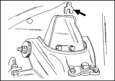
The washers are slotted.
Like the camber angle, the caster angle can be measured by mechanical means. However, optical methods are preferred.

To adjust the pitch angle of the steering axis, loosen the bolts and nuts shown in the illustration and remove or add shims.
Reduction of the longitudinal angle of inclination of the axis of rotation. At the front bolt, the number of washers increases or the number of washers at the rear bolt decreases.
Increase the longitudinal angle of inclination of the axis of rotation. At the front bolt, the number of washers is reduced or the number of washers at the rear bolt is increased.
The difference in the thickness of the front and rear bolt washers should not exceed 3.2 mm.
Since the camber washers are also in the location shown in the illustration, a set of washers is formed, the total thickness of which should not exceed 10.8 mm.
After adjustment, tighten the bolt connection to 155 Nm.
Wheel alignment
The convergence of the front wheels is regulated by changing the length of the steering rods by the same amount. This ensures that the position of the steering wheel spokes is maintained. The distance between the Frontera's front wheels is shorter in front than in the rear (until mid 1995 release) or equal to each other (from the middle of 1995 release).
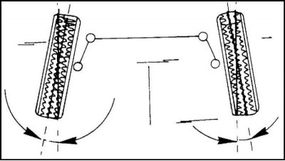
The wheel installation diagram is shown in the illustration.
Toe-in is adjusted using a special template as follows:
1. Check that the tire pressure is correct and that the vehicle is on level ground. The vehicle must not be loaded. The fuel tank must be filled.
2. Press firmly on the front edges of the vehicle several times to bring the suspension elements into position.
3. Set the steering wheel straight.
4. Install template "to zero" and attach it to the front of the wheels at the height of the hubs.
5. Place the measuring rods of the template against the edges of the wheel rims and clamp them.
6. Mark the position of the measuring rods on the wheels with chalk.
7. Check again that the template is installed "to zero".
8. Move the car forward so that the wheels turn half a turn and the chalk lines are again at the height of the hubs, but on the other side of the wheels.
9. Attach the template again to the wheel disks, but now under the car. If the template cannot be applied to the wheel rims, this indicates that the size at the rear needs to be increased. The tolerance for the measured distance is±2 mm.
10. Change the position of the gauge rods so that it can fit between the wheel rims, clamp the rods and remove the template to take a reading. If the template reading is out of range, an appropriate adjustment is required.
11. Raise and place the front of the vehicle on stands.
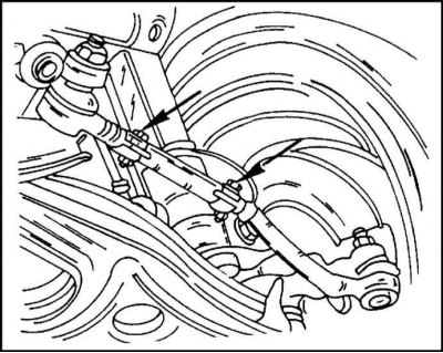
12. Loosen both tie rod clamps
13. Unscrew the tie rods on both sides by the same amount. Turn out in steps of a quarter of a turn.
14. Check the toe adjustment as described above and, when the desired result is achieved, tighten the clamps to 120 Nm. It is necessary to ensure that the lengths of both steering rods are the same. The difference in length should not exceed 5 mm.
15. After adjustment, check that the steering wheel is in the middle position. This is checked by driving the car on a straight road.
Checking the angle of rotation of the front wheels
The steering angle of the front wheels is checked after adjusting the toe. Above the ball joint pin of the lower suspension arm is an adjusting bolt, which adjusts the angle of rotation of the front wheels. A graduated washer is required to control the angle of rotation. Therefore, the work in question is recommended to be carried out in a car repair shop. In this case, it should be borne in mind that the angle of rotation of the inner wheels is 21°50', if the angle of rotation of the outer wheels is 20°.
Visitor comments