
Note: A ball joint puller and a spring puller are required to rebuild the strut. The self-locking nut of the ball joint of the tie rod end, the retaining ring of the drive shaft and the hub nut must be replaced during installation.
Removing
1. Where applicable, remove the caps, then loosen the front wheel bolts. Apply the handbrake, then jack up and support the front of the vehicle on axle stands. Remove the corresponding front wheel.
2. Where applicable, remove the ABS sensor from the steering knuckle as described in Section 9 and disconnect its electrical wiring from the rack.
3. Remove the brake caliper from the steering knuckle as described in Section 9.
Move the caliper to the side and tie it to the body using a piece of wire or rope so that you do not have to disconnect the brake hose.
4. Loosen and remove the self-locking nut of the ball joint that connects the tie rod end to the suspension strut.
5. Remove the ball joint using a special puller.
6. Disconnect the outer end of the drive shaft from the steering knuckle as described in Section 8. Support the drive shaft by tying it to the body with wire or rope. Do not let the drive shaft hang under its own weight.
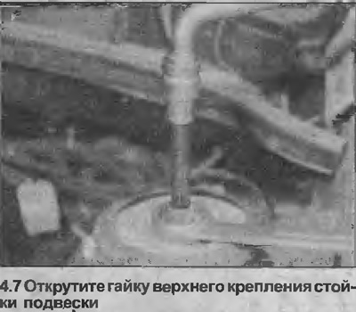
7. Working in the engine compartment, unscrew the top suspension strut nut. To unscrew the nut, it is necessary to hold the suspension strut piston rod stationary with a slotted key (see illustration). Support the strut as the nut may fall out after removing the nut.
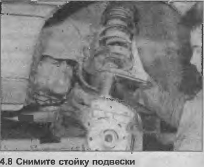
8. Remove suspension strut/steering knuckle assembly (see illustration).
9. If rack overhaul is not required, go to step 30.
Bulkhead
10. Remove the hub, wheel bearing and brake disc shield as described in Chapter 2.
11. Place the suspension strut on a workbench or clamp it in a vise, install a spring extractor and compress the spring to relieve pressure from its top mount. Make sure the puller is securely seated on the spring.
12. Hold the strut piston rod with a slotted wrench and unscrew the rod nut.
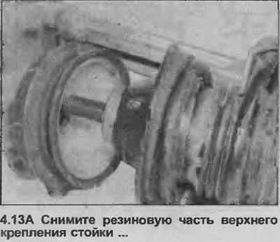
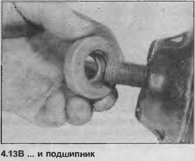
13. Remove the rubber part of the upper strut mount and bearing (see illustrations).
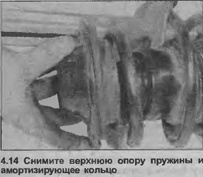
14. Remove the upper spring seat and damping ring, then carefully release the puller and remove the spring (see illustration). Note the correct orientation of the spring.
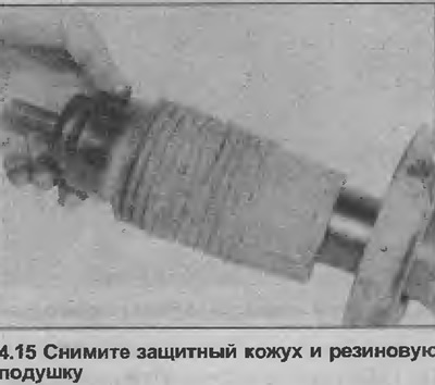
15. Remove the protective cover and the rubber pad inside it from the stand (see illustration).
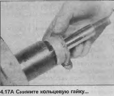
16. To remove the shock absorber cylinder, it is necessary to unscrew the ring nut from the upper end of the telescopic strut. The nut is extremely tight. It is recommended to turn the strut upside down and clamp the nut in a vise, and then, after inserting the bolt into the tie rod bracket, rotate the strut with a long rod.
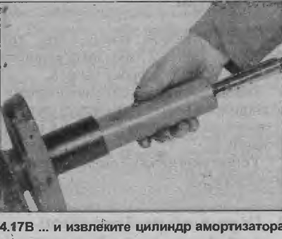
17. Remove shock absorber cylinder (see illustrations).
18. To check the operation of the shock absorber, clamp its lower end in a vise, then move the piston to its full stroke several times. If the shock absorber piston moves jerkily (not exactly) or lack of resistance is felt, replace the shock absorber.
19. Inspect all components for signs of wear and damage and replace if necessary. Pay special attention to the rubber pad and bearing.
20. Begin assembly by inserting the shock cylinder into the strut, then install the ring nut.
21. Clamp the post in a vise and tighten the ring nut to the specified tightening torque specifications.
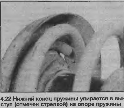
22. Install and compress the suspension spring, making sure that the end of the spring rests on the protrusion on its lower support (see illustration).
23. Install the rubber pad and protective cover.
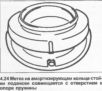
24. Install the upper spring seat and damper ring so that the mark on the damper ring aligns with the hole in the spring seat (see illustration). The hole in the spring seat must be rotated by 90°relative to the end of the spring.
25. Apply a small amount of grease to the bearing, then install it with the side that shows part of the bearing track up.
26. Install the rubber part of the top rack mount.
27. Hold the strut piston rod stationary and tighten the rod nut with the tightening torque specified specifications.
28. Carefully release and remove the spring extractor, making sure that the spring seats are installed correctly. Make sure the lower end of the spring is still resting on the tab on the support.
29. Install the stand as follows.
Installation
30. Install the upper end of the rack into the mount, then screw on the mounting nut and tighten it with a tightening torque regulated specifications the method used in paragraph 27.
31. Connect the outer end of the drive shaft to the steering knuckle as described in Section 8.
32. Insert the ball joint of the tie rod end into the suspension strut and tighten the new self-locking nut with the tightening torque specified specifications.
33. Install the brake caliper on the steering knuckle as described in Section 9.
34. Where applicable, install the ABS sensor on the steering knuckle as described in Section 9 and secure its wiring to the stand.
35. Install the wheel and lower the car to the ground. Finally tighten the wheel bolts and, where applicable, install the cap.
36. Check and, if necessary, adjust the front wheel alignment as described in Chapter 45.
Visitor comments