


Contents: Removal ⬇ Installation ⬇
Note: When installing the drive shaft, use a new hub nut, washer and cotter pin, drive shaft retaining ring and lower arm-to-strut ball joint locking pin. A ball joint puller is required for the job. If the model is equipped with an intermediate shaft, see also Chapter 3.
Removal
1. Where applicable, remove the hubcap, then loosen the front wheel bolts.
Apply the handbrake, jack up and support the front of the car on axle stands. Remove the wheel.
2. Remove the cotter pin from the hub crown nut (at the end of the drive shaft).
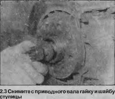
3. Loosen the hub nut. Hold the drive shaft stationary by temporarily installing two bolts in the wheel and inserting a metal rod between them. Remove the nut and washer from the drive shaft (see illustration).
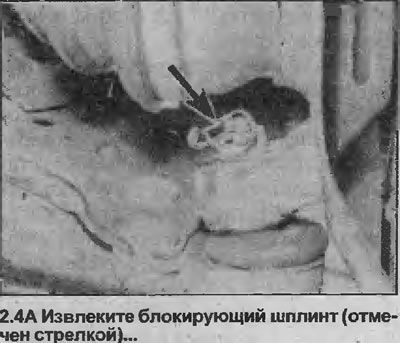
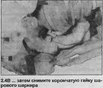
4. Remove the locking cotter pin, then unscrew the castle nut securing the lower arm ball joint to the suspension strut (see illustrations).
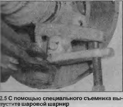
5. Using a special puller, release the ball joint connecting the lower arm to the suspension strut (see illustration).
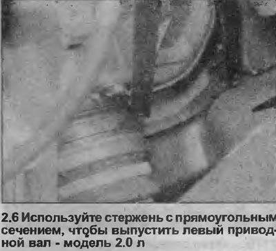
6. To release the inner end of the drive or intermediate shaft from the differential (depending on the model), you will need a lever. To release the right drive shaft, use a flat steel rod with a bevel on one end. The left drive shaft is more difficult to release, you will need a rod with a rectangular cross-section (see illustration).
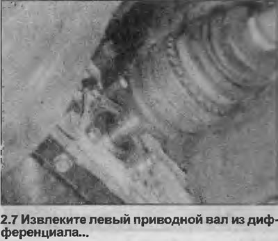
7. Place a pry bar between the drive shaft and the differential housing to release the drive shaft retaining ring from the differential. If necessary, use a drift to push the left drive shaft out. Place a suitable container under the differential to catch any oil that runs out as you remove the drive shaft from the differential. Support the drive shaft so it does not hang under its own weight (see illustration).
8. Plug the holes in the differential to prevent further oil loss and dirt from entering the block.
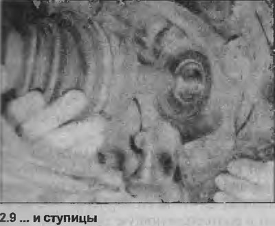
9. Remove the outer end of the drive shaft from the hub and remove the drive shaft from the vehicle (see illustration). If you cannot remove the drive shaft from the hub by hand, lightly tap the end of the shaft with a mallet.
10. Do not allow the vehicle to rest on its wheels while at least one of the drive shafts is removed - this may damage the wheel bearings. If the vehicle must be moved, temporarily insert the outer end of the drive shaft(s) into the hub(s) and tighten the hub nut. In this case, the inner end of the drive shaft(s) must be supported, for example by tying it with twine to the bottom of the vehicle. Do not allow the drive shaft to hang under its own weight.
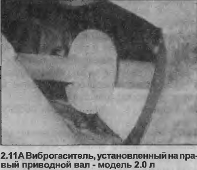
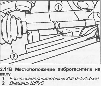
11. Some models are equipped with a two-section vibration damper installed on the right drive shaft. If the vibration damper has been removed for any reason, it must be installed so that the distance between the inner end of the outer CV joint protective boot and the outer end of the vibration damper is as shown (see illustrations).
Installation
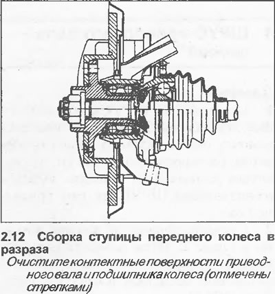
12. Before installing the drive shaft, make sure that the contact surfaces of the shaft and wheel bearing are clean (see illustration).
13. Begin installation by applying a small amount of moly grease to the drive shaft grooves, then insert the outer end of the shaft into the hub. Install a new washer and thread a new hub nut on by hand.
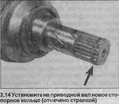
14. Install a new snap ring onto the inner end of the drive shaft, then remove the plug you installed in the differential hole and push the drive shaft into the differential as far as it will go (see illustration).
15. Place a screwdriver or similar tool on the bent edge of the inner drive shaft P joint (not on the metal cover and drive the shaft into the differential (or install it on the intermediate shaft) until the shaft retaining ring is in place - pull the CV joint by the outer edge to make sure of this.
16. Reinstall the ball joint that secures the lower arm to the strut, then install the castle nut and tighten it to the specified torque Specifications. Secure the nut with a new locking pin.
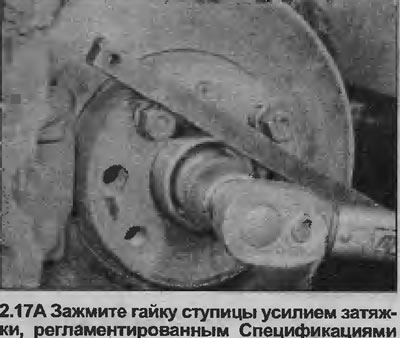
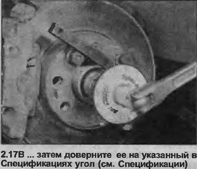
17. Tighten the new hub nut in stages to the torque specified in the Specifications. Hold the drive shaft stationary in the same manner as when removing it (see illustrations). If in this position none of the grooves in the nut align with the hole in the pin, turn the nut another 9° and secure it with a cotter pin.
[Article posted on Internet portal www.OpelBook.ru]
18. Install the wheel, then lower the vehicle to the ground and tighten the wheel bolts. Install the wheel cover where applicable.
19. Check and, if necessary, top up the transmission oil level as described in Section 1.
Visitor comments