
Note: Suitable equipment will be required to support the engine during this procedure. In addition, you will need a ball joint puller. When installing, use a new ball joint nut locking pin that secures the suspension strut to the lower control arm.
Removing
1. The underframe is removed as an assembly with the lower control arms and anti-roll bar.
2. Before removing the subframe, support the weight of the engine near its left bracket. There is a special Opel tool shown in one of the illustrations Section 7A. Alternatively, the weight of the engine can be supported using a winch and hoist. However, in this case, the design of the winch must allow you to support the engine on a jacked up car.
3. Where applicable, remove the caps, then loosen both front wheel bolts. Apply the handbrake, then jack up and support the front of the vehicle on axle stands. Remove the front wheels.
4. Remove the front exhaust box as described in Section 4C. On models with double overhead camshafts (DOHC) unscrew the oil cooler hose bracket from the right side of the subframe.
5. Working on one wheel, remove the locking cotter pin, then loosen the castle nut on the ball joint that connects the lower arm to the suspension strut.
6. Using a special puller, remove the ball joint connecting the lower arm to the suspension strut.
7. Repeat steps 5 and 6 on the second lower arm.
8. Make sure the engine is supported securely, then loosen and remove the two nuts and washers securing the rear engine/transmission mount bracket to the subframe.
9. Support the sub-frame with a jack, laying a piece of board between them to avoid tilting the frame when it is removed.
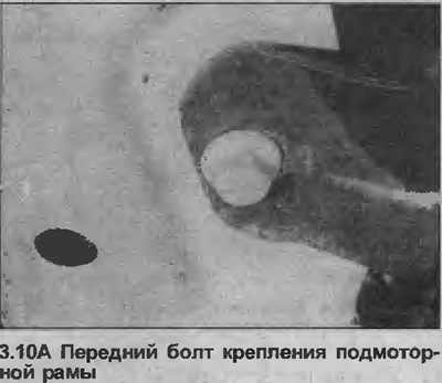
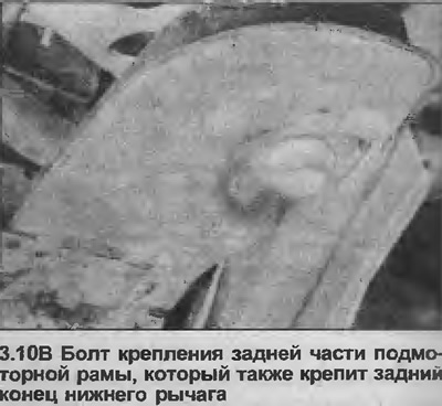
10. Unscrew and remove the six bolts securing the subframe to the bottom of the vehicle. Note that the rear bolts also attach the lower control arms (see illustrations).
11. Lower the jack supporting the subframe and remove the assembly from under the front of the vehicle.
12. If required, remove the anti-roll bar and/or lower control arms from the sub-frame as described in Chapter 8 and chapter 5.
Installation
13. Install in reverse order, paying attention to the following.
14. If the anti-roll bar and/or lower arms were removed from the sub-frame, install them (see Chapter 8 and Chapter 5).
15. Tighten all nuts and bolts with the specified tightening torque specifications, bearing in mind that the rear bolts of the underframe to the bottom must be tightened in stages (see specs).
16. Install the ball joint nuts connecting the lower arms to the suspension struts with new locking cotter pins.
17. Install the front exhaust system as described in Section 4C. On models with double overhead camshafts (DOHC), install the oil cooler hose bracket to the right side of the subframe.
18. Lower the vehicle to the ground, finally tighten the wheel bolts and, where applicable, install the caps.
Visitor comments