
Attention! If one of the struts is to be replaced, the other strut should also be replaced so as not to disturb the suspension geometry.
Removing
1. Apply the handbrake, then jack up the front of the vehicle and place it on axle stands.
2. Remove the front wheel.
3. Remove the brake caliper from the steering knuckle (see Section 9). Tie the caliper to the body so as not to stretch the brake hose.
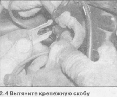
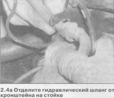
4. Remove the mounting bracket and separate the hydraulic hose from the mounting bracket (see illustrations).
5. Remove the wheel speed sensor from the steering knuckle and disconnect its wiring as described in Section 9.
6. Unscrew the nut and separate the sheer link from the anti-roll bar (see chapter 7), by locking the ball joint with a wrench.
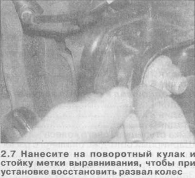
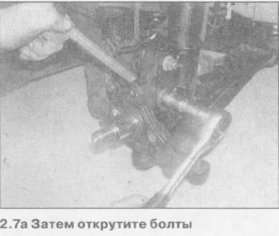
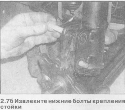
7. Apply alignment marks to the steering knuckle and strut to restore camber during installation, then unscrew and remove the lower strut mounting bolts (see illustrations). Pull the lower suspension arm down to separate the strut from the steering knuckle.
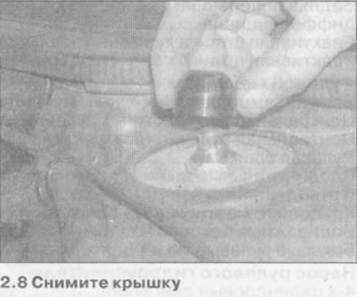
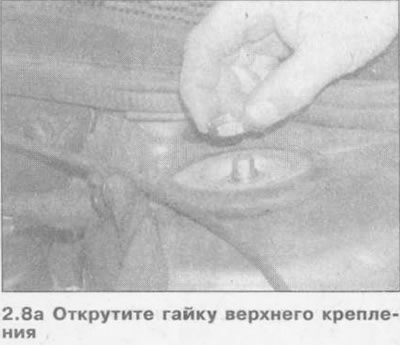
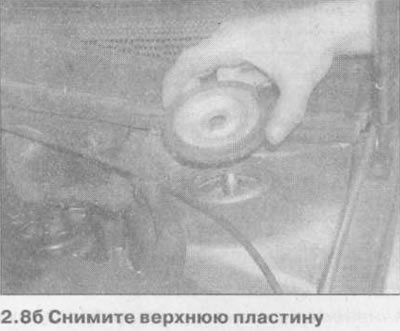
8. While supporting the pole, remove the top mount cover, unscrew the nut, and remove the top plate. Lock the damper rod with the second wrench (see illustrations).
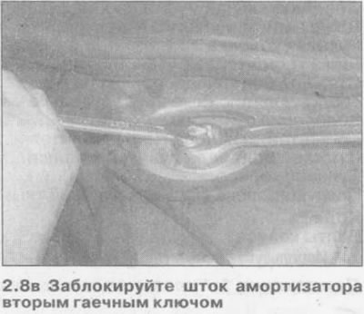
Attention! Do not unscrew the shock absorber rod nut (it becomes accessible after removing the top fixing nut and plate) until the spring removers are installed on the strut.
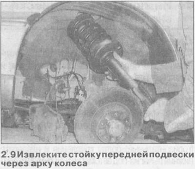
9. Pull the lower end of the strut away from the wheel arch, then lower the strut from the top mount and remove it through the wheel arch (see illustration).
Bulkhead
Attention! You will need a special spring extractor. The use of improvised devices may result in injury.
10. Remove the stand as described in the previous subchapter. If necessary, clamp it in a vise, the jaws of which are equipped with protective pads.
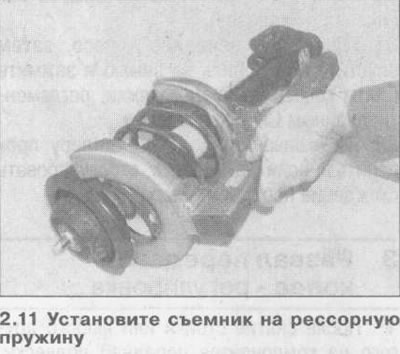
11. Install a spring extractor and compress the spring to release its pressure from the top seat (see illustration).
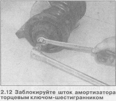
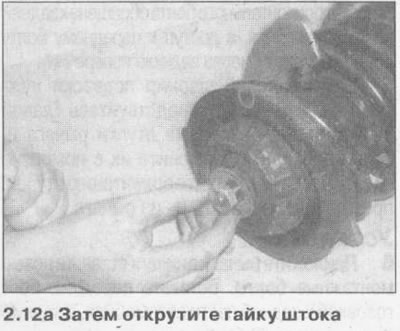
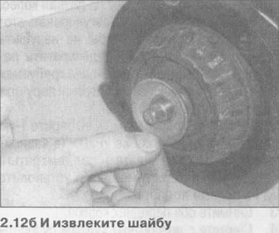
12. After blocking the shock absorber rod with a hex key, unscrew the rod nut and remove the washer (see illustrations).
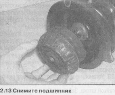
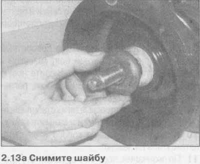
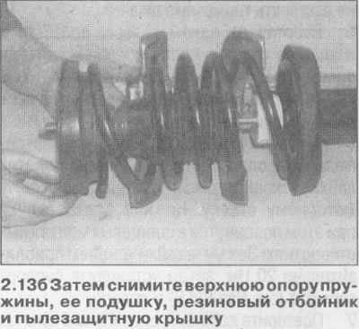
13. Remove bearing and washer (remember its orientation), then remove the upper support 2.13b. Then remove the upper spring seat, its pad, rubber bumper and spring dust cover, its rubber pad, rubber bumper and damper rod dust cap. Remove cushion from lower spring seat (see illustrations).
14. Remove the spring along with the pullers.
15. It is not possible to separate the shock absorber from the strut body, if the shock absorber is defective, the entire strut assembly must be replaced. In this case, the spring, top mount components, bushings, and associated components can be relocated to the new strut.
16. Inspect all components for damage, signs of wear and deformation. Replace components as needed.
17. Inspect the shock absorber for leaks. Check the condition of the shock absorber rod and strut housing. Place the strut in a vertical position and check its operation by moving the stem to its full stroke, and then several times to a short stroke (50-100 mm). In both cases, the resistance should be even and the same. If the piston jerks or the strut resilience changed during the test, or if there is any visible sign of wear, replace the strut.
18. If there is any doubt about the condition of the spring, carefully remove the puller from it and check the spring for deformation and cracks. Replace spring if necessary. Measure the free length of the spring and compare it with the value given in Specifications.
19. If a new shock is being installed, push the stem all the way into the body before reassembly, and then move it full stroke three or four times.
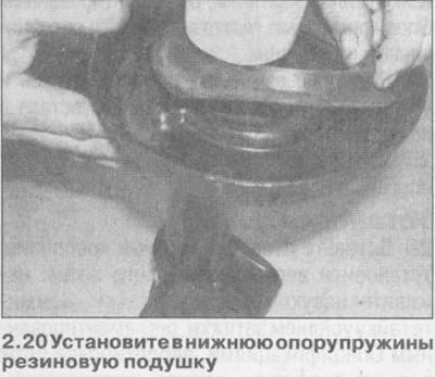
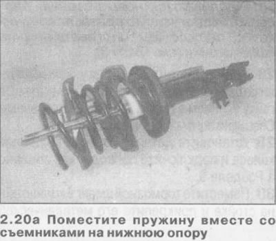
20. Install the rubber pad into the lower spring seat. Make sure the spring is compressed enough to install the top mount components, then place the spring, along with the pullers, on the bottom mount. The lower end of the spring should rest against the ledge of the pillow (see illustrations).
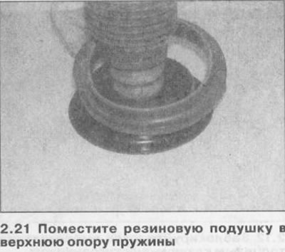
21. Place the rubber pad into the upper spring seat, then install the upper spring seat, bumper and dust cover onto the shock rod (see illustration).
22. Be convinced that the top end of a spring rests against a ledge of a pillow.
23. Install the washer and bearing onto the shock rod and secure them with a washer and a new rod nut. Lock the stem with a hex wrench and tighten the nut to the specified torque specifications. A special adapter may be required.
24. Slowly release the spring extractor and make sure the spring is properly seated in the support pads.
25. Install the front suspension strut as described in the next subsection.
Installation
26. Insert the stand into the top mount. Install the top plate, then screw in a new fixing nut. Tighten the nut with a torque specified specifications, by locking the piston rod with a hex wrench. A special adapter may be required.
27. Connect the bottom end of a rack with a rotary fist and insert new bolts of fastening so that their heads were turned to a forward part of the car. Make sure the lower end of the strut is positioned according to the marks made during removal, then install the new nuts and tighten them to the specified torque specifications.
Note: If the marks are worn or new struts are being installed, check and adjust the front camber before tightening the lower strut nuts (see chapter 3).
28. Connect a sheer link to the end of the anti-roll bar and tighten the nut to the specified torque (see chapter 7).
29. Install the wheel speed sensor and connect the wiring as described in Section 9.
30. Place the brake hose into the bracket on the strut and secure it with a metal clip. Install the brake caliper as described in Section 9.
31. Install the front wheel, then lower the vehicle to the ground and tighten the wheel bolts to the specified torque specifications.
32. When finished, have your dealer check and, if necessary, adjust the toe-in of the front wheels.
Visitor comments