
Transmission AF22/AF33
2. Set the selector lever to position «R».
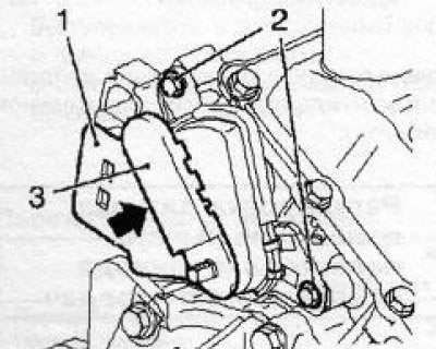
3. In the engine compartment, in order to provide access to the selector lever position sensor, depending on the model, remove the engine cover, release the device from the latches (see resist. illustration) control of the preheating system, unscrew the bolt, loosen the nut and separate the wiring mounting bracket from the sensor.
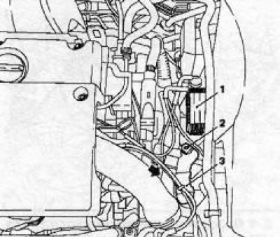
2.3 Device (1) control of the preheating system and fastening of the wiring harness - the fastening nut is indicated by the arrow: 2. Fixing bolt; 3. Mounting bracket
4. Using the KM6042 tool (see resist. illustration) Disconnect the tip of the drive cable from the sensor arm, slide the cable sleeve back and pull it out of the holder. Loosen the sensor arm mounting nut.
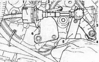
2.4 Disconnecting the drive cable (2) gear shift drive: 1. Coupling; 3. Sensor arm; 4. Fixing nut; 5. Adaptation KM-6042; 6. Rope holder
5. Make sure the selector lever position sensor is set to «R» (lever moved forward to the stop). Use the lever to set the sensor to the position «N». Remove the lever from the sensor axis.
6. Use a flat, long enough metal plate (e.g. caliper ruler), install it so that the side face of the plate is adjacent to the flat slot of the axis of the selector lever position sensor (see resist. illustration), while the plate should be parallel to the mark «N».
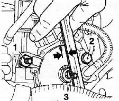
2.6 Adjusting the selector lever position sensor: 1, 2. Mounting bolts; 3. Sensor axis
7. If this condition is not met, it is necessary to loosen 2 fixing bolts (see illustration 2.6) and tighten the sensor to the required value, then tighten the bolts with the required force (see specs).
8. Replace the sensor lever, tighten the fixing nut and move the sensor to the position «R» (lever forward all the way). Connect the cable and reinstall all removed components.
9. If necessary, it is possible to synchronize the position of the selector lever and the sensor, it is performed according to the same principle as the synchronization of the lever and the gearshift mechanism on models with manual transmission (see Chapter 6, Section 8).
10. Inside the car, set the selector lever to the position «R». Remove the front ashtray and gently pry with a small screwdriver to release the latch of the drive cable, thereby separating it from the selector lever.
11. Set the sensor to position "R" pressing its lever forward to the stop, connect the drive cable to the selector lever, snapping the lock. Reinstall the ashtray.
VT20E transmission features (CVTronic)
12. Carry out the operations indicated in paragraphs 2-4.
Note: In addition, it may be necessary to remove the expansion tank. According to the layout conditions on these models, the selector lever position sensor lever moves in a vertical plane.
13. Loosen the fixing nut and disconnect the lever (see resist. illustration).
2.13 Nut (2) lever mounting (1) selector lever position sensor (AT VT20-E)
14. Move the sensor axis to position «N», for which pull the lever up to the stop, and then press it down two clicks.
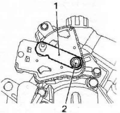
15. Install test tool KM-J-44810-A (see illustration) on the axis of the selector lever position sensor, while the tool must enter the sensor
2.15 Bolts (2) sensor mounts (1) selector lever position sensor (AT VT20-E): 3. Attachment KM-J-44810-A
If this does not happen, it is necessary to loosen 2 bolts and tighten the sensor to the required angle. Tighten the fixing bolts to the required torque. 16 Install in reverse order of removal. Synchronization is performed in the same way as for AT AF23/33 (see above).
Visitor comments