
2. Remove the battery from the tray (see chapter 5). Some models may require removal of the engine cover (see chapter 2) and expansion tank.
3. Remove retaining ring (see resist. illustration) union on the hydraulic line docking station and disconnect the clutch hose. Gently squeezing the lock, put the retaining ring in place in the connector. The sealing ring must be replaced without fail. Seal open ends of tubing and hose immediately to minimize hydraulic fluid loss and prevent dirt from entering the system.
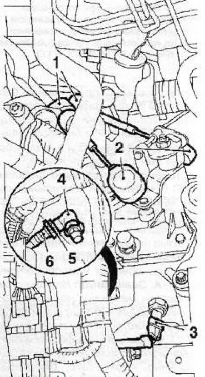
11.3 RKPP supply lines (on the example of manual transmission F17): 1. Fixing sleeves; 2. Tips of cables of a drive of a gear change; 3. Sensor-switch of reversing lights; 4. Hydraulic line docking station; 5. Retaining ring; 6. Clutch feed line hose
Attention: Do not press the clutch pedal with the hose disconnected!
4. Disconnect the electrical wiring from the sensor-switch (see illustration 11.3) reversing lights and release it from the intermediate clips on the gearbox housing.
Note: Depending on the configuration and type of manual transmission, other electrical wiring lines can be connected to or laid through it - they must also be disconnected.
5. Disconnect cable ends (see illustration 11.3) from the gearshift mechanism, remove them from the support brackets and move them aside. If necessary, remove the cable bracket.
6. Turn out 3 top bolts of fastening of transmission to the engine (see resist. illustration).
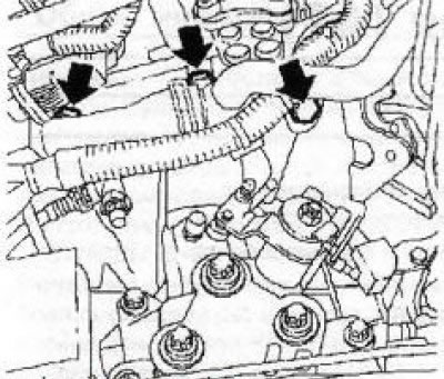
11.6 Top bolts (3) transmission mounts to the engine (on the example of manual transmission F17)
Note: The location of both the upper and lower manual transmission mounting bolts may vary slightly on different models.
7. Hang the power package using lifting equipment (see chapter 10).
8. Fix a radiator and remove an overlay of a forward bumper.
9. Remove the exhaust system (see chapter 4).
10. Install the right engine mount remover (see Chapter 2, Section 5) and remove the front suspension subframe (see chapter 10).
Note: The fixture must remain on the subframe - in this case, it is designed to center the manual transmission during its subsequent installation.
11. Remove the drive shafts, including the intermediate (with appropriate equipment) (see chapter 8).
12. Turn out fixing bolts and remove the left support of the power unit (see chapter 2).
Note: Some models may require the removal of the support mounting bracket as well.
13. Turn out fixing bolts and separate a forward support and an arm of a back support of a suspension bracket of the power unit from a coupling dome.
14. Gradually releasing the hoist, lower the power unit by approximately 5 cm - make sure that the communication lines laid from below are not pinched (hoses and wiring) and make sure that nothing prevents the removal of the box.
15. Remove the lower bolts securing the gearbox to the oil pan and install the MKM-886-A tool on the gearbox (see resist. illustration), by jacking it up. Attach the box to the fixture.
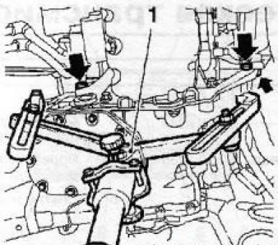
11.15 Installing the KM-886-A fixture (1) - the arrows indicate the side bolts of the transmission (for F17 - three bolts)
Note: Before using the device, carefully read the instructions for its use.
16. Turn out the lower lateral bolts (see illustration 11.15) fastening the box to the engine, disconnect the box from the cylinder block and carefully lower it on the jack.
17. In the absence of a special device, use the help of one or two assistants - unbolt the clutch dome from the engine block, move the gearbox and lower it by hand. Be careful, drain the gear oil if necessary.
18. Installation is made in an order, the return to an order of removal. Don't forget to bleed the clutch drive and adjust the shift drive (see Section 8), and also check the transmission oil level (see chapter 1 and Section 4).
Visitor comments