
Note: The order of procedures performed on a regular basis is described below. Check under the vehicle regularly for signs of fluid leaks. Try not to ignore the facts of the appearance of fluid leaks under the car - such signs indicate the presence of problems that must be immediately eliminated
Attention! When checking the level of any working fluid, the car must be located strictly horizontally! Always use the parking brake when leaving the vehicle!
1. Various hydraulic fluids play the role of working fluids in lubrication, cooling, braking, clutch, heating and air conditioning, windshield washing, etc. Due to the fact that all fluids are subject to thinning and exhaustion over time, and also gradually become contaminated during the normal operation of systems, it is necessary to periodically replace them completely. Please refer to the list of fluids recommended for use in your vehicle before attempting any level adjustment or replacement (see specs). The fluids filled into the systems at the factory are indicated in the technical documentation of each vehicle.
Note: Opel provides a wide range of vehicle options with different types of engines. In connection with this, the location of some test points and the execution of individual elements, both the layout of the engine compartment and the control devices, may differ from those given below. To make it easier to find the filler caps for engine oil, coolant, washer fluid for windows and headlights, as well as the handle of the dipstick for measuring the level of engine oil, are painted yellow.
Engine oil
Visual control of leaks
2. With an oily engine and high oil consumption, check the places where leaks are most likely to develop:
- a) Open the filler cap and check the seal for cracks or damage;
- b) Crankcase ventilation: eg vent hose from cylinder head cover to air intake hose;
- c) Cylinder head cover gasket;
- d) Cylinder head gasket;
- e) Oil removal plug (sealing ring);
- f) Oil pump gasket;
- g) Oil pan gasket;
- h) Front and rear oil seals for camshafts and crankshafts.
Since in the presence of leaks, oil spreads over the surface of the engine, it is difficult to immediately determine the location of leaks. To locate leaks, proceed as described below:
3. Wrap the generator in polyethylene. Spray the engine with a normal cold cleaner and after a short time wash it with water at a car wash.
4. Sprinkle the joints of the engine components on the outside with lime or talc.
5. Check the oil level, top up if necessary.
6. Carry out a test drive to warm up the oil to normal operating temperature.
7. Finally, examine the engine with a lamp and locate leaks by troubleshooting.
Level check
8. When the engine oil level drops to the minimum allowable value in the service display field (see chapter «Controls and methods of operation», Section 16) the corresponding icon will be displayed. Checking the current level of impellent oil is carried out using a dipstick threaded into the guide tube and lowered into the engine to the lowest point of its oil pan.
9. Checking the oil level should be done before the first trip of the day, or after about 5 minutes after stopping the engine.
If the test is performed immediately after the engine is turned off, the results will not adequately reflect the situation, as part of the oil will be distributed to the internal galleries and engine components.
10. Remove the dipstick and: guide tube and dry the blade with a clean cloth or paper towel. Insert the dipstick back into the tube until it stops, then remove it again. After examining the probe blade, estimate the size of the area wetted with oil. The oil level must be between the upper and lower marks on the dipstick blade (see resist. illustrations). If necessary, top up the engine with the appropriate amount of oil of the required grade.
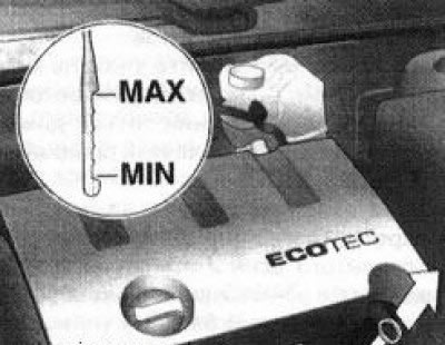
4.10a Propeller for measuring the level of impellent oil - option A
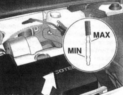
4.10b Engine oil dipstick - option B
11. To raise the level from the bottom (MIN) marks on the dipstick to the top (MAX) required approximately 1 l oil level Lowering the level beyond the lower limit of the permissible range leads to the development of engine oil starvation, which is fraught with serious mechanical damage to the latter. Also, try not to overfill the oil above the upper mark, as this can lead to «throwing» spark plugs or failure of the oil seals of the power unit as a result of an excessive increase in pressure - when overflowing oil, it should be pumped out using a special tool.
12. In order to fill the engine with oil, it is necessary to remove the threaded filler cap. Use a funnel or an oil can with a long spout to avoid splashing oil when filling it into the engine. Fill with oil, screw on and firmly tighten the cap, then start the engine and carefully inspect the drain plug v the oil filter mating surface for signs of leakage. Stop the engine, wait for 5 minutes, during which the oil will drain into the sump, then check its level again
13. Checking the engine oil level is an important preventative engine maintenance procedure. A steady drop in the level is an indication of oil leaks due to failed oil seals, damaged seals, worn piston rings or valve guides. If the oil resembles milk in color or consistency, or there are drops of water in it, this indicates a possible damage to the cylinder head gasket, or the formation of cracks in the body of the head (-OK) or block. The check must be made without delay. When measuring the oil level, always also check its condition. Using your thumb and forefinger, remove traces of oil from the dipstick blade - if there are small metal particles in it, the oil must be replaced.
Engine coolant
Warning! Do not allow antifreeze to come into contact with exposed areas of the body and painted surfaces of the car. Wash off accidental splashes with plenty of water without delay. Remember that antifreeze is a highly toxic liquid and getting it into the body, even in small quantities, is fraught with the most serious consequences, even death. Never leave antifreeze stored in a loosely closed container, immediately collect spilled coolant on the floor. Remember that the sweet smell of antifreeze can attract the attention of children and animals. Consult with local authorities about ways to dispose of used coolant - in many regions of the world there are special points for receiving various kinds of waste. Never drain old coolant down the drain and onto the ground!
14. All models of cars described in this Manual are equipped with a compensation type cooling system operating at excess pressure. The expansion tank of the cooling system, made of translucent plastic, is located on the left (in the direction of travel) rear of the engine compartment next to the brake fluid reservoir and is connected by an overflow hose to the cooling system radiator. As the engine warms up during operation, excess expanding coolant is forced into the reservoir. When cooling, the coolant automatically flows back into the cooling system, which ensures that its level is maintained at a constant value.
15. The coolant level in the expansion tank is checked regularly and when the engine is cold (approximately +20°С) must not fall below the KALT/ COLD mark on the tank wall (see resist. illustration).When the coolant level drops to the minimum allowable value in the field of the service display (see chapter «Controls and methods of operation») the corresponding icon will be displayed. If necessary, make the appropriate adjustment by adding the required amount of fresh mix to the reservoir.
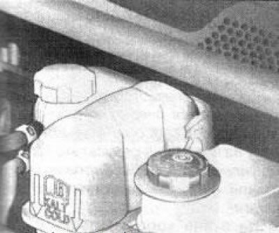
4.15 The coolant level is checked visually through the translucent walls of the expansion tank and should not fall below the KALT / COLD mark
Note: Adding cold coolant must be done after the engine has cooled down.
Attention! To adjust the level, use liquids only of the required composition - carefully study the Specifications for this Chapter! Please note the color of the liquid should be light orange (with prolonged use, it may change slightly and become yellow). The use of antifreezes of various brands as a coolant (the liquid has a characteristic blue-green color - «sea wave») unacceptable! Remember that frequent topping up of drinking / distilled water in the cooling system leads to a gradual dilution of antifreeze and the loss of frost resistance and anti-corrosion properties of the mixture.
16. With a closed cooling system, there is practically no liquid loss. A constant drop in the coolant level usually indicates the development of leaks in the system. Check the radiator, connecting hoses, filler cap, drain plugs and water pump housing for signs of leakage.
17. If it is necessary to remove the cover of the expansion tank, wait for the engine to cool completely, then wrap the neck with a thick layer of rags and slowly unscrew the cover to the first stop. If this produces steam, let the engine cool down a little more, only then remove the cover completely.
Attention! Never remove the cap from the expansion tank when the engine is hot!
18. In addition to the level, always check the condition of the coolant, its concentration (see specs to this Chapter). The concentration of the liquid is checked using a hydrometer with a special scale; it can be purchased commercially or checked at a service station. Even if the fluid does not change externally, the corrosion inhibitors included in its composition are depleted over time, so the condition of the coolant should be checked regularly in accordance with the vehicle maintenance schedule (see section 1).
Windshield/Headlight Washer
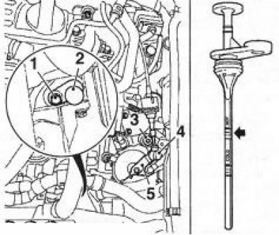
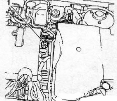
19. Windshield / headlight washer fluid is poured into a special reservoir located in the left front corner of the engine compartment between the battery and the left front headlight. The filler cap is located on the upper beam of the front end of the engine compartment next to the left headlight (see resist. illustration), - to measure the liquid level, the tank is equipped with a measuring probe. In temperate regions, clean water can be used as a glass washer fluid, but the tank should not be more than 2/3 full to compensate for the expansion of the water when it freezes during frosts. When operating the vehicle in harsh environments, use only proprietary windshield wipers that provide an adequate drop in the fluid's freezing point. To avoid freezing of the glass when washing in cold weather, preheat it by blowing air passed through the heater heat exchanger.
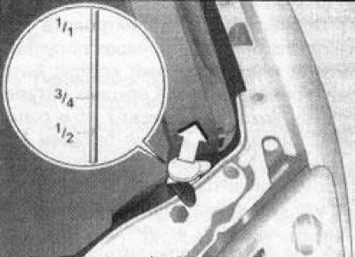
4.19 Windshield/Headlight Washer Reservoir Cap
Attention! Rules for using the liquid are usually printed on the container label. In no case do not use antifreeze used in the cooling system to add glass washer fluid - the latter is aggressive towards the paintwork of body panels!
Battery electrolyte
Warning! The basis of the battery electrolyte is ACID! Failure to take measures in case of electrolyte contact with the skin or eyes can lead to burns or even loss of vision - immediately wash them with plenty of water, seek medical help in a timely manner! Wear safety goggles and gloves when handling the battery! Wash your hands thoroughly after performing work, do not store the rags used to wipe the surfaces of the battery. Explosive gas is released during battery operation! It is forbidden to use open fire sources, smoking near the battery!
20. Modern rechargeable batteries, subject to the minimum requirements for care and operation under normal conditions, do not require additional maintenance and are calculated, on average, for 4 years. Periodically, especially during the hot season, check the electrolyte level in the battery.
Attention! Do not allow the battery to operate for a long time with an insufficient electrolyte level - this can lead to overcharging of the battery, destruction of the plates and a significant reduction in its service life!
21. The electrolyte level is checked visually, through the translucent plastic case of the battery. The level in ALL sections of the battery must be between the MIN and MAX marks on the battery case. If the electrolyte level is not visible through the case, check it through the filler holes (if available) battery sections, it must reach the lower edge of the filler sleeve or cover the internal mesh of the battery section (depending on battery design). If it is necessary to adjust the electrolyte level, add the required amount of DISTILLED water.
Note: Do not fill in too much water, excess electrolyte is removed using a special hand pump (pears). After completing the level adjustment, close the filler holes tightly and wipe the battery surfaces with a rag soaked in an alkaline solution.
Brake and clutch fluid
22. Reservoir for hydraulic (brake) liquid is located in the engine compartment near the rear wall above the main brake cylinder (GTZ) and is used to store a reserve supply of fluid in the hydraulic paths of the drive of both the brake mechanisms and the clutch.
23. The liquid level inside the tank is clearly visible through the translucent walls of the latter and must be maintained between the MIN and MAX marks, slightly below the top (see resist. illustration).
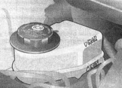
4.23 The level of the working fluid in the GTZ tank is clearly visible through its translucent walls
24. If it is necessary to adjust the fluid level, carefully wipe the reservoir cap and the area around it with a clean rag to prevent dirt from entering the hydraulic system.
25. When pouring liquid into the tank, make sure that it does not splash onto the surrounding painted surfaces of the body elements. Add only fresh fluid of the specified grade (see specs at the beginning of this chapter), - the mixing of two liquids of different grades is in no case unacceptable and may lead to failure of the corresponding system!
Attention! Brake fluid is highly chemically aggressive - do not let it get into your eyes and onto painted surfaces of body panels! Do not add to the system brake fluid that has stood for more than one year or has been stored in a loosely closed container. Remember that brake fluid is very hygroscopic ie. has the ability to absorb moisture from the air, as a result of which the effectiveness of the brake system can be dangerously reduced!
26. At the stage of level adjustment, you should also carefully check the condition of the liquid and the internal walls of the tank. In case of dirt deposits, solid foreign particles or water droplets, the system must be emptied and filled with fresh brake fluid (see chapters 6 and 9).
27. Once the reservoir is filled to the correct level, fit the lid tightly onto the reservoir.
28. Remember that the level of brake fluid in the reservoir gradually drops as the friction linings of the brake pads actuate, but this decrease is always very small. If the fluid has to be added too often, therefore, there is a leak in the system, the source of which must be identified without delay, and the cause eliminated, carefully inspect all brake lines and their fittings (see Section 9). A drop in the fluid level in the clutch hydraulic reservoir indicates the development of leaks in the tract, including the slave cylinder.
29. With significant losses of brake fluid, when the reservoir is completely empty, after eliminating the cause of the leak, it is necessary to pump the hydraulic paths of the brake system and the clutch engagement drive.
Power steering fluid
30. Depending on the model, the fluid reservoir may be located in the engine compartment directly above the steering gear or in the rear niche of the right wing.
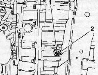
31. Liquid level control is carried out using marks on the dipstick built into the tank filler cap (see resist. illustration). The level must be between the MIN·marks (A) and MAX (b). At «cold» liquid, its level should not fall below the lower mark.
Note: Depending on the configuration, some covers are equipped with stops - these are cross-shaped plastic plates on the dipstick designed to prevent splashing and leakage of fluid when driving on rough roads or with a large roll.
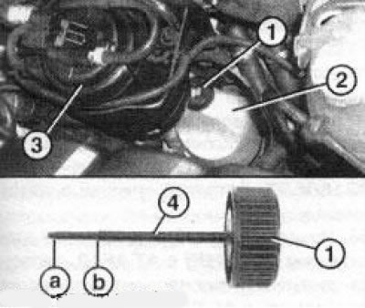
4.31 Reservoir (2) power steering fluid (installation option on diesel models): 1. Filler cap; 3. Fuel filter; 4. Probe: a. Minimum level label; b. Max Level Label
32. Try not to allow the liquid level to go beyond the lower limit of the allowable range.
33. If necessary, make an appropriate level adjustment by topping up the reservoir neck with the correct grade of hydraulic fluid (see specs).
34. If the need to adjust the fluid level occurs regularly and frequently, check for signs of leakage of the steering pump, rack and pinion housing, as well as all connecting lines of the hydraulic path of the system and their union connections.
Gearbox oil
Note: Checking and adjusting the level should be carried out only in case of detection of oil leaks from the manual transmission. In other cases, they are not necessary.
35. First of all, it is necessary to make a thorough visual inspection of the box for possible oil leaks. To do this, clean the body of the box from dust, dirt and traces of oiling, sprinkle possible leaks with talcum powder. The most likely leaks are:
- Mating surfaces of the engine and manual transmission;
- Seals of the primary shaft of the manual transmission;
- Filling hole plug;
- Drain plug. before the control check, it is necessary to warm up the manual transmission oil well during a short (up to 30 km) trips.
36. Drive the car onto a flyover or inspection hole, or jack it up and place it on supports in a strictly horizontal position. If an oil leak is detected, first eliminate its cause, and then adjust the oil level in the manual transmission.
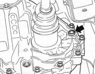
4.37 Location of the manual transmission control hole
37. Thoroughly wipe the surface of the box crankcase around the control plug. If necessary, dismantle the protective casing of the engine compartment. The inspection hole is located on the left rear of the gearbox (behind the input shaft) (see illustration).
38. To check, it is necessary to unscrew the plug of the control hole and, using a bent under 90" wire, measure the oil level in the gearbox crankcase - the oil level should not fall below the edge of the control hole by more than 20 mm (minimum allowable level).
Attention! On models equipped with Z20NET and Y30DT engines with a 6-speed manual transmission, transmission oil level control is not provided, because. when installing a manual transmission on a car, the oil level is located above the control hole (about 1.3 l).
39. If necessary, the level is adjusted using a special syringe / lubricator through the hole for installing the sensor-switch of the reverse lights (Manual transmission F17/F17+), or through the control hole (Manual transmission F23/F35/F40) - disconnect the wiring connector (with appropriate equipment) and remove the sensor/plug. Oil should be filled in until its level reaches the lower edge of the control hole.
Note: Transmission oil has a high viscosity - it takes time for it to be evenly distributed throughout the entire volume of the gearbox housing. Make adjustments in several stages, do not fill in too much oil at once, periodically check its level.
If oil starts to leak over the edge of the check hole, allow the excess to drip off.
40. At the end of the adjustment, screw the control hole plug into place with a force of approximately 4 Nm and tighten it with a wrench about 1/8 more, maximum 3/8 turn (45°-135°). Then screw in the reversing light switch sensor, after replacing the gasket, and tighten it firmly 20 Nm.
41. For ventilation of the crankcase, a special breather with a cover is screwed into the gearbox housing. Each time you inspect the manual transmission, check the breather cap - it should be loosely seated on the breather. When the breather is clogged (fixed cover) increased pressure is created in the crankcase of the manual transmission, which can cause a malfunction of the manual transmission, as well as lead to extrusion of seals and leakage of transmission oil.
42. After completing the work, remove traces of oil from the gearbox, remove the tool from under the car and lower the latter to the ground if it was jacked up or raised on a lift. During the first trips, check the box for leaks.
ATF
43. Correct ATF level is one of the critical performance parameters for AT equipped models. An excessive drop in the ATF level can cause the rotation converter to slip, while an excessive amount of fluid leads to its foaming, leakage and is fraught with transmission failure.
44. Checking the ATF level can be done with the transmission warmed up to normal operating temperature (15-20 km run, 72-80°С).
Attention! Do not check the ATF level immediately after driving the vehicle at high speeds, in urban conditions in hot weather, or after towing a trailer - let the fluid cool down for about 30 minutes beforehand!
45. Park the car on a flat, level surface with a hard surface, firmly cock the parking brake. If the engine is cold, start it and warm it up at idle. With the engine running, depress the foot brake pedal and move the AT selector lever through all positions in turn, finally returning it to position «R». On CVTronic models, leave the lever in each position for approximately 10 Seconds.
46. On models equipped with AT AF23 and AF33 (engines Z22SE/ Z32SE/Y22DTR), if necessary, first disconnect the shift cable and wiring harness from the AT body, move them to the side. Remove the fixing bolt (see resist. illustration) and remove the dipstick.
4.46 Checking and adjusting the AFT level on AT AF 23 and AF 33 - the arrow indicates the marks for checking the fluid level when the transmission is warm: 1. Bolt for fastening the eyepiece; 2. Measuring probe; 3. Filler plug; 4. The tip of the drive cable; 5. Drive arm
Attention! Never remove a sealed, hex/pentagon bolt, otherwise the AT will need to be overhauled or replaced.
47. Wipe the blade thoroughly with a clean rag and insert the probe back into the guide tube, seating firmly on the neck. Remove the dipstick from the neck again - the liquid level should be between the marks next to the inscription «HOT» (see illustration 4.46). If necessary, make the appropriate adjustment by adding to the transmission through a special filler hole (see ibid) liquid of the required grade.
Attention! Before refueling, it is necessary to shake the liquid in the packaging container well and mix it thoroughly. Failure to comply with this requirement may lead to the formation of foam during the movement of the car and the failure of the transmission!
Add ATF in small portions in several steps, each time checking the level.
48. When installing on a car AT AF 23 / AF 33 together with the Y30DT engine, in order to free access to the ATF level dipstick, it is necessary to remove the front engine mount, - the oil level at a temperature70-80'C must be between the marks next to the inscription «NOT».
Note: To raise the level from the bottom mark on the dipstick to the top mark, approximately 0.3 liters of liquid is required. To access the filler hole, you must remove the battery from the tray (see chapter 5).
49. On models equipped with AT CVTronic - VT 20-E, if necessary, remove the engine crankcase protection (diesel models) and put under the drain hole (see resist. illustration) a suitable container to collect the liquid and remove the control bolt.
4.49 Drain hole AT CVTronic VT 20-E: 1. Control bolt; 2. Drain plug
Attention! To check the oil level, only the control bolt must be unscrewed, and not the entire oil drain plug!
50. When the bolt is turned out, a certain amount of oil will drain into the substituted container. Wait until the oil stops dripping - at a normal level, approximately 0.5 l oils.
51. Tighten the control bolt with the required force. Remove the cover (see resist. illustration) filler hole and add the required amount of liquid, and it must first be mixed with the additive (see specs).
4.51 Lid (1) filler hole
Note: Depending on the temperature of the oil, different volumes of oil are poured (see specs). The oil temperature is measured using the Opel - TECH - 2 diagnostic tool.
52. On models equipped with Z18XE engines with AT CVTronic VT20-E, it is required to carry out at each next maintenance (see section 1) additive regeneration. Remove the cover (see illustration 4.51) filler hole and add 8 servings (syringes) additives Opel93160537. Tighten the cap to the required torque.
53. On models equipped with the Z19DT engine (H) CATAF40, the ATF level is also checked» on models with AT CVTronic - VT 20-E.
54. Upon completion of the adjustment, reinstall all removed components and tighten the threaded connections to the required torque (see Specifications).
55. A description of the procedure for checking v replacing ATF is given in Chapter 7.
Visitor comments