
Note: Before beginning any fuel filter maintenance procedures, thoroughly wipe the area around the fuel filter seat to prevent the risk of dirt entering the fuel system path. To collect spilled fuel, place a rag under the filter, or install a suitable drain container.
Attention! Do not allow diesel fuel to come into contact with the surfaces of the generator, starter, cooling system hoses, engine mounts and wiring harnesses!
1. The fuel filter is installed on the rear bulkhead of the engine compartment.
Sludge/Water Drain
2. On engines with a displacement of 1.9 liters, before draining the sediment from the fuel filter (see resist. illustration) it is necessary to disconnect the terminal clamps from the battery, observing the requirements given in Chapter 5.
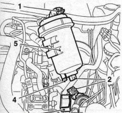
8.2 Engine fuel filter Z19DT (H): 1. Plug connector for fuel heating system; 2. Plug connector for fuel temperature sensor (with appropriate equipment); 3. Tank for draining sludge; 4. Filter drain plug; 5. Filter housing
3. Disconnect plug connectors (see illustration 8.2) fuel heating system and fuel temperature sensor (with appropriate equipment). Then, without disconnecting the fuel hoses, remove the filter housing from the mounting clamp. Place a suitable container underneath to drain the sludge/water.
Note: Try not to shake the filter so that the sediment does not mix with the top layer of fuel.
Loosen the drain plug about one turn and allow the fuel to drain into the prepared container. Do not tighten the plug until clean fuel comes out of the hose - it is usually enough to drain about 100 ml.
Attention! The fuel must not drain completely from the filter. At the end of the operation, fix the filter housing in its original place and dock the plug connectors.
4. On Y20DTH / Z22DTR / Y30DT engines, to drain sediment / water from the fuel filter, it is necessary to put on the drain valve (see resist. illustration) in the lower part of the filter housing, a piece of hose of a suitable size, - lower the other end of the hose into a clean container, preferably with transparent walls. Slightly loosen the pinch bolt on the filter cover and then the valve. Draining of sludge/water is done as described above. At the end of the operation, close the valve and tighten the pinch bolt on the filter cover (6 Nm).
Note: Do not overtighten, otherwise sealing gasket may be damaged and leakage will occur. It is not necessary to bleed the fuel system to remove air after draining the sediment/water (see paragraph 17).
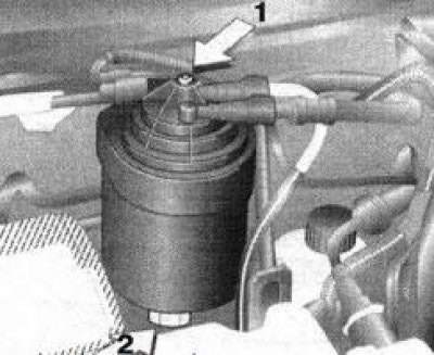
8.4 Fuel filter for Y20DTH/Z22DTR/Y30DT engines: 1. Fuel filter pinch bolt; 2. Drain valve
Attention! On diesel engines of 2.0 and 2.2 liters, if the filter is completely empty, the air from the fuel system will have to be removed using a special device!
5. Remove the waste container. Use a clean rag to pick up spilled fuel. Connect the battery. Finally, check all weakened components for signs of leak development.
Replacing the working element of the fuel filter
6. Disconnect the battery and completely drain the fuel from the filter (see above).
7. Disconnect all plug connections of the system (if they were not disconnected when draining the fuel).
8. Disconnect the fuel hoses from the filter housing (see resist. illustration), - try not to damage the special connectors, use a special tool from Opel for this (KM-796-A or Hazet 4501-1). After disconnection, close the free ends of the hoses with plugs to avoid fuel spillage and air ingress into the fuel system.
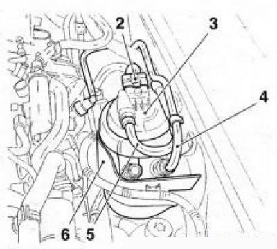
8.8 Diesel fuel filter (on the example of Z19DT (H)): 2. Plug connector for fuel heating system; 3. Fuel filter housing; 4. Outlet fuel hose; 5. Inlet fuel hose; 6. Filter attachment
9. Slide upwards and remove the fuel filter housing from the mount.
10. To replace the filter element of engines with a working volume of 2.0/2.2/3.0 l, it is necessary to unscrew the coupling bolt (see resist. illustration) and disassemble the filter. A certain amount of fuel remains in the replaceable element - after removing it, put it in a suitable container, drain the remaining fuel from the filter housing there. Wipe the cover and filter housing with a clean cloth.
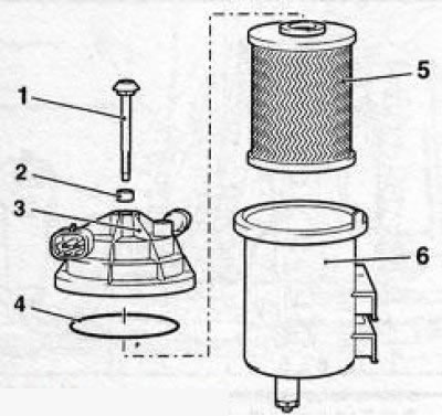
8.10 Fuel filter design for Y20DTH/Z22DTR/Y30DT engines: 1. Coupling bolt; 2. Sealing gasket; 3. Filter cover; 4. Cover gasket; 5. Replaceable filter element; 6. Filter housing
11. Insert a new replacement filter element into the housing and fill the filter almost to the upper edge of the housing with clean diesel fuel.
Attention! The ingress of even a small amount of sand and dirt on the inner surface of the replacement element can lead to failure of the high pressure fuel pump (injection pump). Replace the gaskets, assemble the filter carefully and tighten the pinch bolt to 6 Nm.
Note: Do not overtighten, otherwise the sealing gasket of the filter cover may be damaged.
12. Filter design for Z19DT engines (H) presented on ref. illustrations 8. 12a. To replace the filter element, it is necessary to use a special tool (Opel-EN-46784-020) clamp the filter housing in a vice, then, using a special key (Opel-EN-46784010) (see resist. illustration 8.12b), release the pressure ring on the filter cover. If special tools are not available, fix the fuel filter housing in a vise using suitable gaskets or curly jaws, and release the clamping ring with a hammer and a wooden block - the blows on the block should be applied carefully, alternately fitting it to the various protrusions of the ring. -
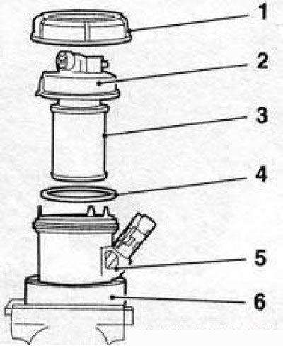
8.12a Engine fuel filter design Z19DT (H): 1. Clamping ring; 2. Fuel filter cover; 3. Replaceable filter element; 4. Sealing gasket; 5. Filter housing; 6. Device for clamping the filter housing in a vise (Opel-EN46784-020)
Attention! When disassembling the filter without using a special tool, be especially careful - you can damage the thread or the edges of the clamping ring, which in turn will lead to a violation of the tightness of the seal!
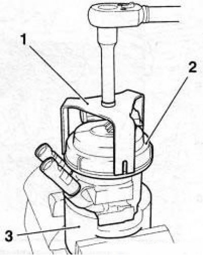
8.12b Dismantling the fuel filter for Z19DT engines (H): 1. Special key (Opel-EN-46784ОУ); 2. Clamping ring; 3. Device for clamping the filter housing in a vise (Opel-EN46784-020)
13. Remove the filter cover with replaceable element, remove the O-ring, and by turning the replaceable element 50°counterclockwise, disconnect it from the cover. Wipe the cover and filter housing with a clean cloth.
14. After replacing the replaceable element, the filter is assembled in the reverse order - do not forget to replace the seal and fill the filter with fuel.
Note: The filter cover can only be installed in the housing in one position to avoid incorrect assembly. The clamping ring is tightened with a force of 30 Nm.
15. After assembling the filter, carefully install it in the mount, remove the plugs and connect the fuel hoses, then connect the electrical wiring to the filter and connect the battery.
16. Upon completion of all operations with the fuel filter, it is necessary to start the engine and let it idle. Check the fuel system for leaks. If the engine does not start, bleed the air from the fuel supply system (see below).
Bleeding air from the fuel system
17. Air will be removed from the system automatically when turned on «ignition» and starting the engine. However, if there is too little fuel in the filter, the engine may not start or the engine may stop shortly after starting.
18. In this case, on Z19DT engines (Hf and Y30DT turn on and off three times «ignition» each time leaving it on for at least 3 seconds. When turned on «ignition» the electric fuel pump is activated, with the help of which fuel circulates throughout the fuel circuit, air is removed and the fuel filter is filled. Restart the engine - hold the ignition key until the start occurs, but no more 30 seconds. If the engine does not start again, turn off «ignition» and after a while repeat the bleed procedure.
Note: On the Y30DT engine, you can skip pre-bleeding and simply hold the ignition key until the engine starts. But if this does not happen within about 1 minute, the engine control module will deactivate the starter to prevent damage to the starter. Wait 1-2 minutes and turn on the starter again.
19. On Y20DTH and Y22DTR engines, if the engine refuses to start after the fuel tank or fuel filter is completely empty, it is necessary to remove air from the system using an external fuel pump (for example, Orel-KM-948).
Attention! Attempts to remove air by starting the starter can lead to the failure of the injection pump!
20. Before starting the procedure, make sure that the fuel reserve in the fuel tank at least 5 l, all elements of the fuel system are checked for leaks and the battery is sufficiently charged.
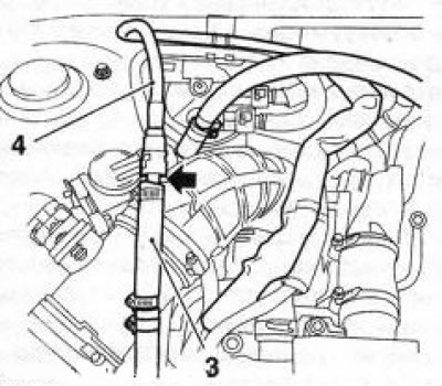
21. Substitute a suitable container to collect escaping fuel. After disconnecting the quick connector, separate the front fuel line (see resist. illustration) from the end connector and release the end connector from the holder.
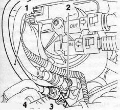
8.21 Disconnecting the front fuel line (1): 2. Holder for fuel lines; 3. Fuel line end connector; 4. Quick connector
22. Connect the pressure hose of the vacuum pump (see illustration 8.22a) to the end connector of the front fuel line, and the suction hose of the pump to the front fuel line (see illustration 8.22b).
8.22a Connecting the pressure hose (1) vacuum pump to end connector (2) front fuel line - the arrow indicates the quick coupling
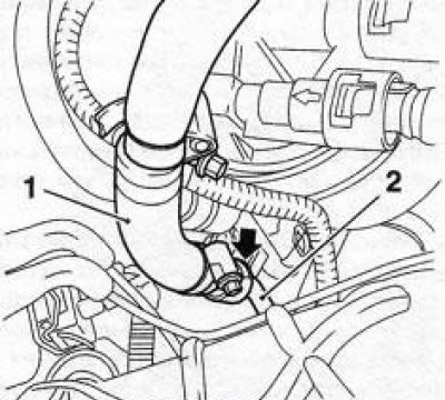
8.22b Suction hose connection (3) vacuum pump to front fuel line (4) the arrow indicates the quick coupling
23. Turn on the vacuum pump for about 3 minutes, then, without turning off the pump, start the engine with a starter.
Note: Engine cranking by starter is allowed for no more than 40 seconds. If the engine does not start within this time, wait approximately 20 seconds, then repeat the starting process.
24. After starting the engine, leave the vacuum pump on for some more time. Turn off the pump and turn off the engine.
25. Connect the front fuel line in reverse order.
26. Start the engine and check the fuel system for leaks.
Visitor comments