


Contents: Control and measuring instruments ⬇ Instrument cluster field ⬇ Service indicator display ⬇
The instrument lighting is activated when the running lights are turned on. The brightness of the lighting is selected using the rotary control located on the switch panel to the left of the steering column.
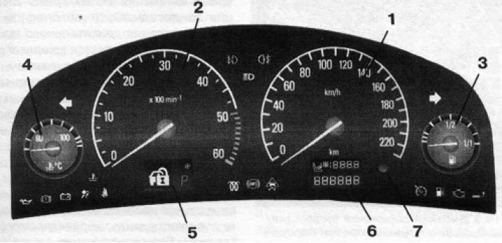
16.1 Layout of meters, control lamps and indicators in combination:; 1. Speedometer; 2. Tachometer; 3. Fuel gauge; 4. Coolant temperature gauge; 5. Service indicator/gearbox mode selection display; 6. Odometer/resettable trip meter display; 7. Button for resetting the current mileage counter
Control and measuring instruments
The arrangement of the gauges in the instrument cluster is shown in Figure 16.1.
Speedometer
The speedometer is located on the right side of the instrument cluster (see illustration 16.1) and shows the vehicle speed in km/h.
Attention! Always observe the speed limit established by the Road Traffic Regulations (RTR), follow the speed limit signs!
Tachometer
The tachometer is located on the left side of the instrument cluster (see illustration 16.1) and shows the engine crankshaft speed in thousands of revolutions per minute (the arrow reading should be multiplied by 100)To avoid engine failure, do not exceed the maximum permissible crankshaft speed (the tachometer needle should never enter the red zone of the scale).
Attention! If the tachometer needle approaches the red sector of the scale, you should immediately shift to a higher gear!
Fuel gauge
The fuel gauge dial is mounted in the instrument cluster to the right of the speedometer (see illustration 16.1) and serves for visual monitoring of the remaining fuel supply in the tank.
The device shows the APPROXIMATE fuel level in the tank. The error of the fuel gauge readings is minimal when the car is in a strictly horizontal position. When the car is moving on winding or hilly roads, the error of the device increases. When the ignition is turned off, the gauge needle moves to the lower mark of the scale.
Low Fuel Warning Light
 in the lower right corner of the instrument cluster (see below) is activated when there is a small amount of fuel left in the tank (the meter's arrow drops to the lower left sector of the scale), and warns about the beginning of using the fuel reserve. Activation of the control lamp in flashing mode warns about the inadmissibility of further reduction of the amount of fuel in the tank - at the first opportunity fill up the tank.
Attention! It is strictly forbidden to drive until the tank is empty - this can lead to failure of the catalytic converter of exhaust gases!
When the fuel in diesel models is completely used up, it is necessary to remove air from the fuel system; this is a rather labor-intensive procedure, so try to replenish the fuel supply in the tank in a timely manner.
Coolant temperature gauge
The fuel gauge dial is mounted in the instrument cluster to the left of the tachometer (see illustration 16.1) and serves for visual monitoring of the engine operating temperature.
The meter readings may vary within the operating temperature range, depending on the ambient air temperature and the vehicle's driving mode. With normal operation of all systems, the coolant temperature should not exceed the range of 80-100°C (with a warm engine).
When operating, increased pressure is created in the cooling system, which allows the vehicle to continue operating for some time when the coolant temperature exceeds 100'C - the corresponding indicator lamp on the instrument panel should light up (see Section 16). Reduce engine load at the first opportunity, stop the vehicle on the side of the road if necessary, check the coolant level and reduce the temperature. If you do not take appropriate measures in case of overheating, further movement of the vehicle may lead to serious damage to the power unit.
Odometer/Resettable Tripmeter Display
The display is mounted in the lower part of the instrument cluster under the speedometer dial (see illustration 16.1). The odometer and resettable mileage counter display fields are located one above the other: the odometer at the bottom and the counter at the top. The odometer records the total mileage of the vehicle since it was put into operation. The total mileage readings are constantly present on the display. The resettable mileage counter allows you to track the vehicle's mileage since the last reset.
The resettable mileage counter is reset when the ignition is on using the button built into the instrument cluster to the right of the display (see illustration 16.1).
If equipped, the front passenger seat occupancy recognition indicator is integrated into the upper left corner of the display
 , which lights up when the ignition is turned on and goes out after about 4 seconds, confirming that the system is working properly. Failure to turn off indicates a malfunction of the front passenger seat occupancy recognition system (except in the case of installation of a special Opel child seat with transponders in the front seat).
Service indicator/gearbox mode selection display
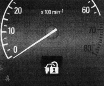
16.2 Service indicator display
The service indicator display is mounted in the lower part of the instrument cluster under the tachometer dial (see illustration 16.2) and is designed to display information about the condition and operation of some vehicle systems and the mileage remaining until the next maintenance (TO). In addition, on models equipped with an automatic transmission (AT) (see sections 23 and 24), the display has additional fields (see illustration 16.3) to indicate the operating mode of the gearbox. When the selector lever is switched to the appropriate position, the selected gearbox mode is indicated in the lower right field of the display:
- R - Parking
- R - Reverse
- N - Neutral gear
- D - Automatic smooth switching mode.
- A - Automatic step-by-step switching mode (CVTronic)
- 1-5 - Manual mode - the gear currently engaged (AT Active Select system)
- 1-6 - Manual mode - currently engaged gear (CVTronic)
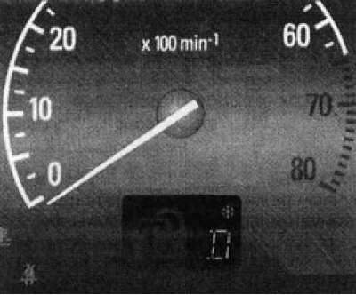
16.3 Service indicator/gearbox mode selection display
When the winter driving mode is activated, an indicator appears in the upper right field of the display
 .
.
Control lamps, indicator lights and service indicator display pictograms
Note: Some indicator/warning lamps are built into the corresponding switches located on the instrument panel/center console of the vehicle, their operating procedure is given in the description of the corresponding system.
Note: In case of modification of the model range and installation of modern systems and equipment, the combination of control lamps and indicators may be supplemented.
The vehicle's instrument cluster assembly contains a whole range of control lamps and indicator lights (see illustration 16.1), with the help of which the driver receives important information about the serviceability/malfunction of the main units and systems of the vehicle (control lamps), and can also monitor the correct activation/deactivation of the corresponding units and systems (indicator lights). Below is a list and description of the control lamps, indicator lights, and service indicator display icons built into the instrument cluster.
Note: Depending on the model and equipment, not all of the following indicator/warning lights may be installed on your vehicle.
Instrument cluster field
 Engine oil pressure warning light. The light is activated when the ignition is turned on. If this light fails to turn off after the engine has started, or if it is activated while driving, this indicates a dangerous drop in engine oil pressure. If the light is activated while the vehicle is moving in a constant or flashing mode, pull off the road in a safe place and turn off the engine immediately.
Warning! Operating the vehicle with the warning light on may cause serious damage and engine failure!
Check the engine oil level and make adjustments if necessary. If the warning light comes on when the oil level is normal, the car should be taken to a service station for more detailed diagnostics and necessary repairs.
Note: The engine oil pressure warning light is not intended to monitor the oil level in the system. The dipstick is intended to check the oil level (see Chapter 1). In addition, when the engine oil level drops, a corresponding pictogram appears on the service indicator display (see below).
 Low brake fluid level indicator/parking brake applied indicator. When the ignition is switched on, the indicator light comes on continuously with the parking brake applied, reminding the driver to release it before driving. If the indicator light continues to light after the parking brake is released, or comes on while driving, this usually indicates an excessive drop in the brake fluid level - you should stop and check the brake fluid level in the brake fluid reservoir, and carefully inspect the components of the hydraulic brake system for leaks. If necessary, eliminate the causes of leaks and add fresh fluid to the reservoir. If the brake fluid level is normal, contact a service station specialist to check the operability of the corresponding components of the electrical circuit.
Attention! Driving a car with a faulty braking system is not allowed under any circumstances!
 The charge indicator lamp is activated when the ignition is turned on and should go out a few seconds after the engine is started. If the lamp does not turn off, or if it turns on while driving, this indicates a fault in the charging system - you must pull off the road in a safe place, turn off the engine and check the condition of the multi-rib belt (see Chapter 1). A broken or loose belt may be accompanied by malfunctions of the engine cooling system, and on diesel models, in addition, by the cessation of the vacuum booster.
Warning! Do not continue driving if the belt is loose, damaged or missing - contact the nearest service station!
 Supplementary Restraint System (SRS) failure indicator lamp. When the ignition is turned on, the indicator lamp should light up. If the SRS is working properly, the lamp will go out approximately 4 seconds after switching on. If the lamp does not switch off, does not light up at all, or is activated while driving, this may indicate a malfunction in the airbag circuits or automatic emergency seat belt tensioners. The car should be taken to a service station as soon as possible to perform the necessary diagnostics and perform the appropriate repairs.
 Coolant temperature warning light. When the light comes on while the engine is running, it warns you of a dangerous increase in coolant temperature - stop the car immediately in a safe place and measure the coolant level, make the appropriate adjustment.
Warning! Prolonged driving with the indicator light on may result in engine failure due to overheating!
 The "Fasten seat belt" indicator lamp reminds the driver to fasten the seat belt. The lamp is activated when the ignition is switched on and remains lit until the driver's seat belt buckle is fastened.
Note: An additional warning gong will sound to remind you to fasten your seat belts.
 The diesel engine preheating indicator lamp lights up only at low ambient temperatures when the ignition is switched on, indicating that the preheating system is activated and goes out after the glow plugs have warmed up to the required temperature. The engine should not be started until the indicator lamp goes out.
Note: If the lamp does not go out for a long time, this may indicate a malfunction in the preheating system - contact a service station.
 The anti-lock brake system (ABS) indicator light comes on briefly when the ignition is turned on (at this point, the ABS self-diagnostic system is activated, accompanied by a characteristic noise) and should go out after a few seconds. The lamp's failure to turn off, as well as its activation while driving, indicates a malfunction of the ABS - at the first opportunity, it is necessary to diagnose the brake system using special equipment or drive the car to a service station to perform the necessary repairs.
Note: When the indicator lamp is on, the anti-lock brake system will not operate, but the brake system will continue to function normally.
 Indicator of deterioration of road surface traction/disabling of the anti-skid (ESP)/anti-skid (TS) system. On models equipped with ESP/TS, this indicator lights up when the ignition is turned on. If the anti-skid system is working properly, the indicator goes out after a few seconds.
When the vehicle is moving, the indicator is activated in flashing mode when the ESP/TC system is switched on, thereby warning the driver about the deterioration of the road surface grip properties and that the vehicle wheels are on the verge of slipping, while the vehicle movement is automatically slowed down.
Note: When the ESP/TC is operating, a characteristic noise can be heard in the engine compartment.
The indicator's refusal to turn off, as well as its activation during movement in constant mode, confirms the fact of the anti-skid/anti-slip system being turned off or malfunctioning - you can continue driving, but the vehicle's directional stability may deteriorate when the road surface properties change. In case of a system malfunction, contact the service station specialists as soon as possible.
 This indicator serves to confirm the correct activation of the fog lights (with appropriate equipment). When the headlights are turned off, the indicator goes out.
 This indicator serves to confirm the correct activation of the fog lights (with appropriate equipment). When the lights are turned off, the indicator goes out.
 This indicator serves to confirm that the high beam headlights are activated correctly. When the headlights are switched to low beam, the indicator goes out.
 Tempostat-controlled movement indicator. This indicator (with appropriate equipment) lights up briefly when the ignition is turned on and should go out after a few seconds. When driving, it is activated and remains lit for the entire time the cruise control is activated.
 The low fuel indicator lamp warns you to refuel the fuel tank when the fuel gauge needle drops to the lower left sector of the scale (see above).
 The engine management system malfunction indicator lamp ("Check engine") is activated when the ignition is switched on and should go out a few seconds after the engine has started. If the lamp does not switch off, or if it is activated while driving, this indicates a malfunction of the engine management system - the permissible toxicity standards of exhaust gases may be exceeded. Contact an Opel service station to identify and eliminate the malfunction. Activation of the indicator lamp in flashing mode with the engine running indicates a malfunction that may lead to failure of the catalytic converter. If it is necessary to continue driving, reduce the fuel supply with the gas pedal so that the indicator lamp stops flashing and lights continuously - contact a service station as soon as possible.
 If equipped accordingly, this indicator serves to confirm the correct operation of the turn signals when the vehicle is towing a trailer. It is activated in flashing mode at the same frequency as the turn signals. Refusal to activate when the turn signal is on warns the driver that one of the turn signal lamps on the trailer or towing vehicle has failed.
 The arrow-shaped direction indicator/hazard warning lights glow green and are used to monitor the correct operation of the corresponding direction indicators.
The direction of the indicator arrows coincides with the selected direction of change of the vehicle's course. The indicators operate in a flashing mode with a frequency corresponding to the frequency of flashing of the direction indicators. Rapid flashing of one of the indicators indicates that the lamp of one of the indicators of the corresponding direction indicator has burned out; replace the burned-out lamp as soon as possible (see Chapter 12), in order to avoid emergency situations on the roads. The activation of the hazard warning lights is accompanied by the simultaneous flashing of the indicators of both turn signals.
Service indicator display
The service indicator display is mounted in the lower part of the instrument cluster under the tachometer dial (see above). When certain events occur, corresponding icons appear in the display field, informing the driver about malfunctions in the systems controlled by electrical sensors and electronic systems. Below is a list of the main icons.
 Activation of the immobilizer system. This icon lights up when the ignition is switched on and should go out after a few seconds. If the indicator remains lit, the key is not recognized by the system as authorized. Remove the key from the ignition and try again. In case of another failure, try to switch on the ignition with a spare key and contact an Opel service center for assistance.
 Malfunction in the electrohydraulic power steering system. The appearance of this icon in the display field warns of the cessation of the power steering function - it is possible to continue driving, but remember that turning requires much more effort than when driving a car under normal conditions.
 Malfunction of the automatic headlight tilt adjustment device. On models with the corresponding configuration, this icon is displayed when the automatic headlight tilt adjustment device fails. The malfunction must be rectified immediately! Continuing to drive with a failed adjustment device in conditions of limited visibility (twilight, night time) creates a risk of blinding drivers of oncoming and preceding vehicles, as well as the risk of an accident due to deterioration of visibility. Eliminate the malfunction immediately and contact a service station that has special equipment for adjusting headlights.
 Parking assistance system failure. Activation of the pictogram in flashing mode (flashing) indicates the occurrence of failures in the system due to external interference - contamination of sensors, external sources of ultrasound (for example, jackhammers, garbage trucks) etc. When the cause of the failure is eliminated, the system returns to normal operating mode - the indicator goes out.
If the icon is constantly lit, this indicates a system malfunction - contact an Opel service station.
 Electronic start/engine/gearbox immobilizer system failure/water in fuel filter (diesel models). The appearance of this icon in the display field with the engine running indicates a malfunction in the electronic equipment of the engine or automatic transmission. The electronic system switches to emergency mode, fuel consumption may increase and the ability to drive the car is limited. In some cases, the malfunction can be eliminated by turning off and starting the engine again. If the icon continues to appear with the engine running, you should seek assistance from a service station.
Note: A short, single flashing of the pictogram has no significance.
Activation of the pictogram in flashing mode after switching on the ignition indicates a fault in the engine start immobilizer system; the engine cannot be started. In this case, switch off the ignition and switch it on again. If the pictogram continues to flash, try to start the engine with the spare key and contact a service station for assistance. On diesel models, activation of the warning lamp may also indicate the presence of water in the fuel filter; at the same time, a corresponding message appears on the service indicator display (see above). The water must be removed from the filter; if necessary, contact an Opel service station.
 This icon comes on when the boot/tailgate is opened and remains on until the boot/tailgate is closed.
 Failure of lamps of external lighting devices. If equipped, this pictogram lights up when one or more lamps of external lighting devices burn out. Check all devices and replace the failed lamp (see Chapter 12).
 Brake lining wear indicator. On models equipped with brake linings with built-in wear sensors, this icon lights up to warn the driver that the brake linings have worn down to the minimum permissible thickness and need to be replaced (see Chapter 9).
 Engine oil level indicator. The icon lights up when the engine oil level drops to the minimum permissible value - check the oil level and make the appropriate adjustment if necessary (see Chapter 1).
 Coolant level indicator. The icon lights up when the coolant level drops to the minimum permissible value - check the fluid level, make the appropriate adjustment if necessary (see Chapter 1).
 Service interval indication. This icon is displayed simultaneously with the mileage remaining until the next maintenance, and reminds the driver of the need to bring the car to a service station for the relevant work. More detailed information is provided in Chapter 1.
 Tyre pressure drop. On models with the appropriate equipment, this icon lights up in red to warn of a dangerous drop in air pressure in the corresponding tyre - you must immediately pull off the road in a safe place and check the air pressure in the tyres. If the icon lights up in yellow, the pressure drop is insignificant, check the pressure at the first opportunity and make the appropriate adjustment. Detailed information on pressure monitoring systems is provided in Section 27.
 Tire pressure monitoring system malfunction. On models with the corresponding configuration, the appearance of this icon in the display window while the vehicle is moving indicates a malfunction in the tire pressure monitoring system - contact a specialist as soon as possible.
 This pictogram serves to warn about the opening/not closing tightly of one or more doors of the vehicle.
Visitor comments