
Instrumentation
The layout of meters in the instrument cluster is shown in illustration 16.1.
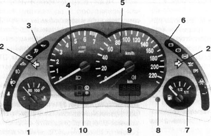
16.1 Layout of meters, control lamps and indicators in combination: 1. Coolant temperature meter; 2. Turn signal/alarm indicators; 3. Left window of control lamps/indicators; 4. Tachometer; 5. Speedometer; 6. Right window of control lamps/indicators; 7. Fuel gauge; 8. Button for resetting the resettable counter of the current mileage / setting the time readings / displaying service indication; 9. Odometer/resettable current mileage/hours/service indication display; 10. Display of the selected transmission mode (AT/Easytronic)
Note: Depending on the year of manufacture of the car and its configuration, the appearance of the instrument cluster as a whole and individual instruments may differ from those shown in the accompanying illustrations.
Speedometer
The speedometer is placed in the central part of the instrument cluster on the right (see illustration 16.1) and shows the vehicle speed in km/h.
Attention: Always follow the speed limit established by the Rules of the Road (SDA), follow the speed limit signs!
At the bottom of the speedometer field there is a built-in odometer/resettable current mileage/hours/service indication display (see below).
Tachometer
The tachometer is located in the central part of the instrument cluster on the left (see illustration 16.1) and shows the engine speed in thousands of revolutions per minute (arrow reading should be multiplied by 1000). In order to avoid engine failure, it is forbidden to exceed the maximum permissible speed of the crankshaft (the tachometer needle should never enter the red zone of the scale).
Attention: If the tachometer needle approaches the red sector of the scale, you should immediately switch to a higher gear!
Fuel gauge
The fuel gauge dial is mounted in the instrument cluster to the right of the speedometer (see illustration 16.1) and serves for visual monitoring of the amount of fuel remaining in the tank.
The device shows the APPROXIMATE level of fuel in the tank. The error in readings of the fuel gauge is minimal when the car is in a strictly horizontal position. When driving on winding or hilly roads, the error of the instrument increases. When the ignition is turned off, the meter needle moves to the zero mark of the scale.
The control lamp for the minimum fuel reserve go in the lower left sector of the meter dial (see illustration 16.2) activated when there is a small amount of fuel left in the tank (the meter needle drops to the left extreme sector of the scale), and warns about the beginning of the use of the fuel reserve. Activation of the control lamp in flashing mode warns of the inadmissibility of a further decrease in the amount of fuel in the tank - fill the tank as soon as possible.
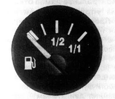
16.2. Fuel Gauge Dial
Attention: It is strictly forbidden to drive to an empty tank - this can lead to failure of the catalytic converter of exhaust gases (see Section 28)!
When running out of fuel on diesel models, it is necessary to remove air from the fuel system (see chapter 1).
Coolant temperature meter
The fuel gauge dial is mounted in the instrument cluster to the left of the tachometer (see illustration 16.1) and serves for visual monitoring of the temperature regime of the engine. The meter functions only when there is sufficient coolant in the engine cooling system.
Meter readings may vary within the operating temperature range, depending on the ambient temperature and vehicle driving mode. During normal operation of all systems, the temperature of the coolant should not go beyond the range of 80-100°C (with warm engine) (see illustration 16.3). During operation, increased pressure is created in the cooling system, which allows the vehicle to continue to operate for some time when the temperature of the coolant exceeds 100°C. Reduce engine load as soon as possible, stop vehicle if necessary, check coolant level and reduce temperature. If you do not take appropriate measures in case of overheating, further movement of the car can lead to serious damage to the power unit.
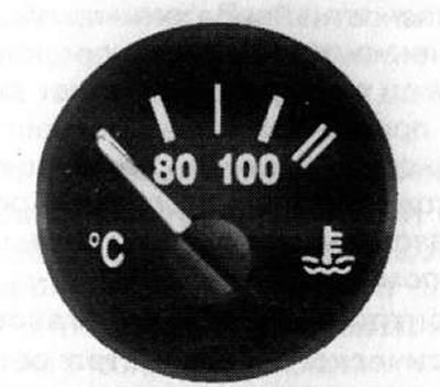
16.3. Coolant Temperature Gauge Dial
Odometer/Resettable Odometer/Hour/Service Indication Display
The indication display is built into the lower part of the speedometer dial (see illustration 16.1). The indication fields of the odometer and the resettable odometer are located one above the other: the odometer is at the bottom, the counter is at the top.
The odometer records the total mileage of the vehicle since it was put into service. The total mileage is permanently displayed on the display. The resettable trip meter allows you to track the distance traveled by the vehicle since the last reset.
Resetting the resettable current mileage counter is done by briefly pressing the reset button built into the instrument cluster to the right of the speedometer dial (see illustration 16.4).
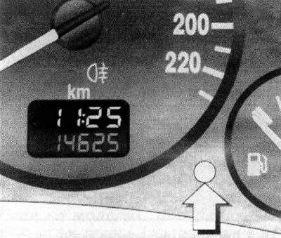
16.4. Button for resetting the resettable counter of the current mileage/setting the clock
On some models, the display may also show the current time. With this configuration, to reset the trip odometer, hold down the reset button for about 2 seconds. If the display is activated in the time display mode, first switch it to the counter display mode by briefly pressing the reset button.
The procedure for correcting the clock is shown below.
Setting/adjusting the clock (with appropriate equipment)
To set/correct the clock, switch the display to the time indication mode by briefly pressing the reset button (see illustration 16.4).
Press and hold the reset button of the resettable counter for about 2 seconds, the current time display in the clock is activated in flashing mode. Set the required value by short pressing the same button. Then press the button again and hold it for about 2 seconds - now the current time in minutes is activated in flashing mode. Set the desired value by briefly pressing the button. After another 2 second pressing of the button, the clock will switch to the normal display mode.
Note: If the battery has been disconnected from the car's on-board network for some time, then the next time the power is turned on, the chronometer readings will be reset.
Display indicating the selected transmission mode
On models equipped with AT/Easytronic (see Sections 23 and 24), the display is mounted in the lower part of the tachometer dial field (see illustration 16.5) and is designed to display information about the currently selected mode of operation of the gearbox.
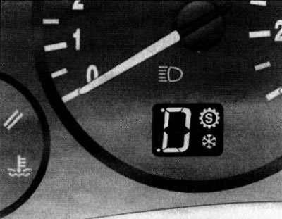
16.5. Display indicating the selected transmission mode
When the selector lever is switched to the appropriate position, the selected transmission mode is displayed on the left side of the display:
- P - Parking
- R - Reverse
- N - Neutral gear
- A - Automatic mode (Easytronic)
- M - Manual mode (Easytronic)
- D - Automatic mode (AT)
- 1-4 - Currently engaged gear (AT)
- 1-5 - Manual mode, currently engaged gear (Easytronic)
Note: On models equipped with the Easytronic system, the mode indication flashes for several seconds, if, with the engine running and the brake pedal not depressed, the selector lever is switched to position A - it is necessary to start moving or move the lever to position «N».
When activating special transmission control modes (see Section 25) the corresponding indicators are displayed on the right side of the display field:
Pilot lamps, light indicators
Note: Some warning lamps/indicators are built into the appropriate switches located on the instrument panel/center console of the vehicle, and their operation is described in the description of the respective system.
A whole complex of control lamps and indicator lights is built into the assembly of the car's instrument cluster (see illustration 16.1), with the help of which the driver receives important information about the serviceability / violation of the functioning of the main units and systems of the car (pilot lamps), and can also monitor the health of the activation / deactivation of the corresponding nodes and systems (indicator lights).
Below is a list and description of the warning lamps and indicator lights installed in the instrument cluster.
Note: Depending on the model and equipment, not all of the following warning lamps/indicators may be installed on the vehicle.
Left window of control lamps/indicators of a combination of devices
Note: The need to fasten seat belts will be additionally reminded by a signal gong.
Note: A short one-time lamp ignition does not matter.
Activation of the control lamp in flashing mode after the ignition is turned on indicates a malfunction in the engine start blocking system, the engine cannot be started. In this case, turn off the ignition and turn it on again. If the lamp continues to flash, you should try to start the engine using the spare key and contact a workshop for help.
The activation of the warning lamp in flashing mode with the engine running indicates a malfunction that can lead to failure of the catalytic converter. If it is necessary to continue driving, reduce the fuel supply with the gas pedal so that the control lamp stops flashing and burns continuously - contact a service station as soon as possible.
Caution: Operating the vehicle with the warning light on can cause serious damage and engine failure!
Check engine oil level, correct if necessary (see chapter 1). If the control lamp works at a normal oil level, the car should be driven to the service station for more detailed diagnostics and the necessary remedial repairs.
Note: The engine oil pressure indicator lamp is not designed to control the oil level in the system, this function is performed by another indicator (see below). In addition, a dipstick is used to check the oil level (see chapter 1).
Right window of control lamps/indicators of a combination of devices
Attention: Do not continue driving if the belt is loose, damaged or missing - contact your nearest service station!
Note: On Easytronic equipped models, the warning light will flash for a few seconds after the ignition is turned off if the parking brake lever has not been engaged.
If the warning lamp continues to burn after releasing the parking brake, or works while driving, this usually indicates an excessive drop in the brake fluid level, you should stop and check the brake fluid level in the GTZ reservoir, and also carefully inspect the components of the hydraulic circuit of the brake system for leaks. If necessary, eliminate the reasons for the development of leaks and add fresh fluid to the reservoir. If the brake fluid level is normal, contact the service station to check the operation of the relevant components of the electrical circuit.
Attention: Under no circumstances should you drive a vehicle with a faulty brake system!
Note: When the control lamp is on, the anti-lock brake system will not operate, while the brake system continues to function normally.
EPS The control lamp of failures in system of the electric amplifier of a wheel. The activation of this warning lamp warns that the power steering has ceased to function - you can continue to drive, but remember that when cornering, much more effort will be required than when driving in normal conditions.
While the vehicle is moving, the indicator is activated in flashing mode when the EERDS system is turned on, and thereby warns the driver about the deterioration of the grip properties of the road surface and that the vehicle's wheels are on the verge of slipping, while the vehicle automatically slows down.
Note: During the operation of the ESPTC, a characteristic noise is heard in the engine compartment.
The failure of the indicator to turn off, as well as its activation while driving in a constant mode, confirms the fact of a malfunction and disconnection of the anti-skid / traction control system - you can continue the trip, however, the vehicle's directional stability may deteriorate when the properties of the road surface change. In the event of a system malfunction, contact a service station as soon as possible.
If on models equipped with ESP, the power supply was interrupted / the battery was disconnected, when the power supply is restored, the indicator will be lit in a constant mode - the system should be tuned. For more information about ESP/TC operation, see Section 25.
Instrument cluster field
Note: If the lamp does not go out for a long time, this may indicate a malfunction in the preheating system - contact a service station.
Visitor comments